|
|
VDH - Head casting Last updated: 30 Nov 2016 |
The head casting worries me the most as there are is no room for mistakes while machining it. I tried putting a bar through the core hole to line things up (as per the instructions in the book), but the core varies in size so this didn't work out to be a good idea.
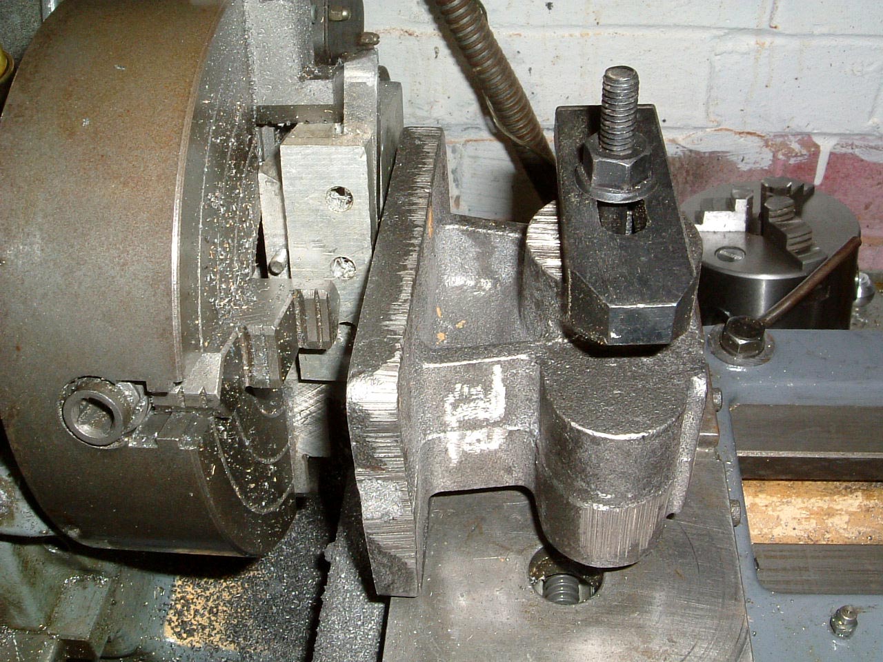 |
10-Mar-2005: The casting has had the front face machined, now the base is getting the same treatment. The improvised cutter looks tatty but does the business! |
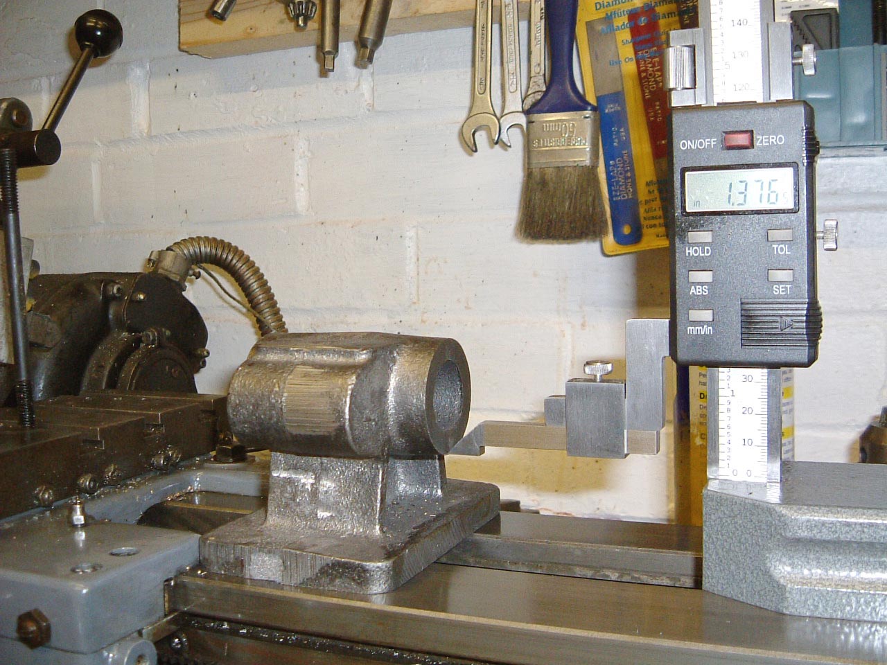 |
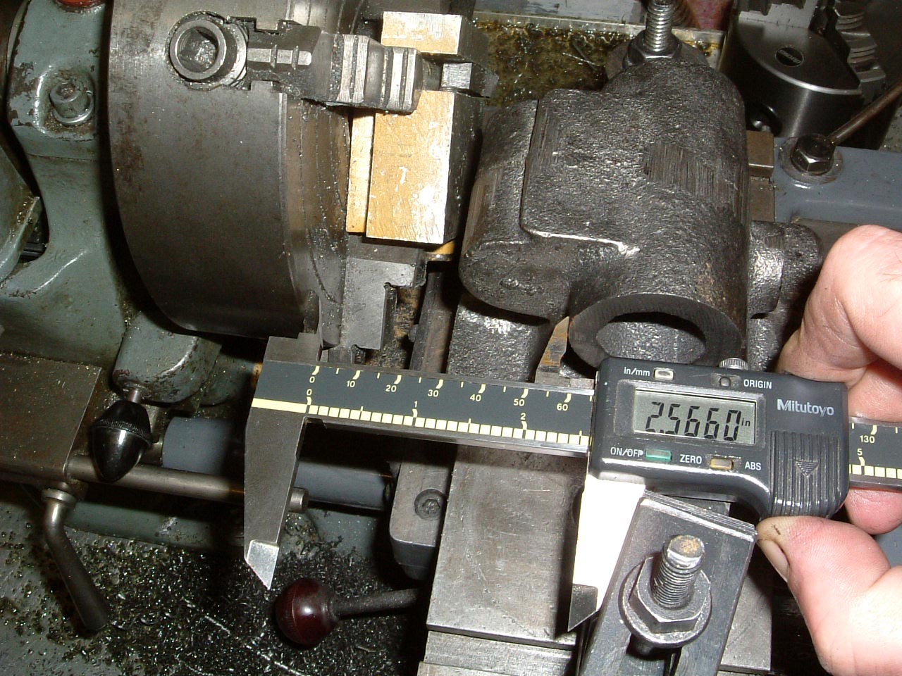
After skimming the base flat, some measurements are being taken just to ensure that the front face and base have been machined square to where the bore is supposed to go. Measurements are taken at each end and noted. |
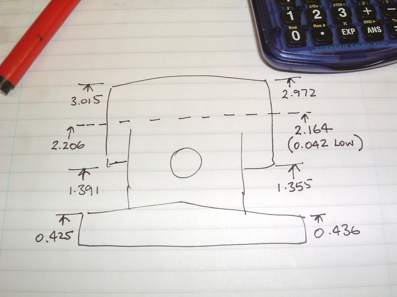 |
The measurements will allow the amount of 'tip' required on the front face to be calculated in order to get the bore level. In this case, a correction of 0.042" will be required. |
 |
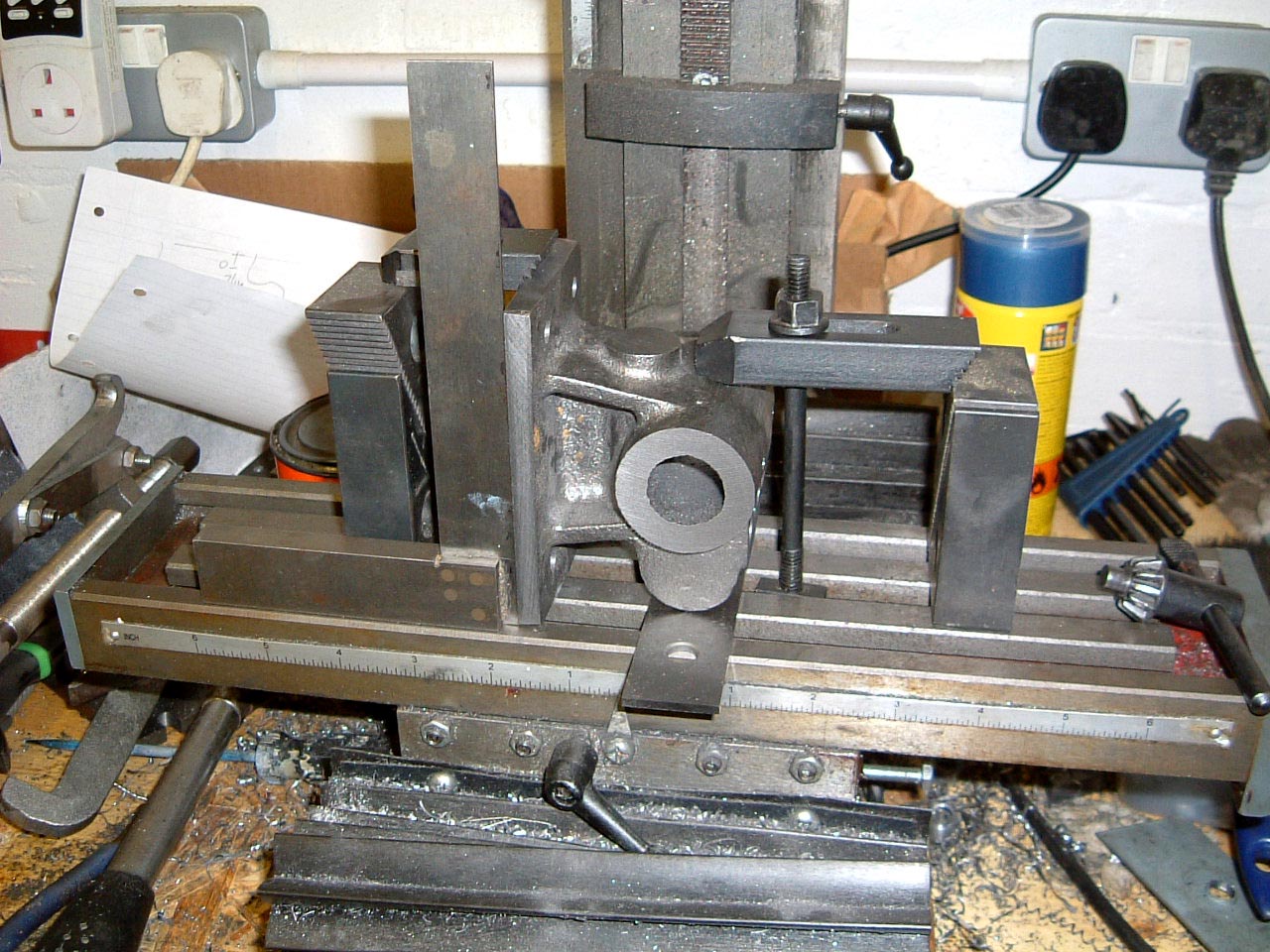
12-Mar-2005: The front face and base have now been re-machined to correct rotational errors in the Z axis. Thomas' book uses an angle plate to get the next edge of the foot machined. This is my 'cheap and cheerful' version keeping the casting clamped down on the base, and using a square to get the correct 90 degree angle between the edges. |
 |
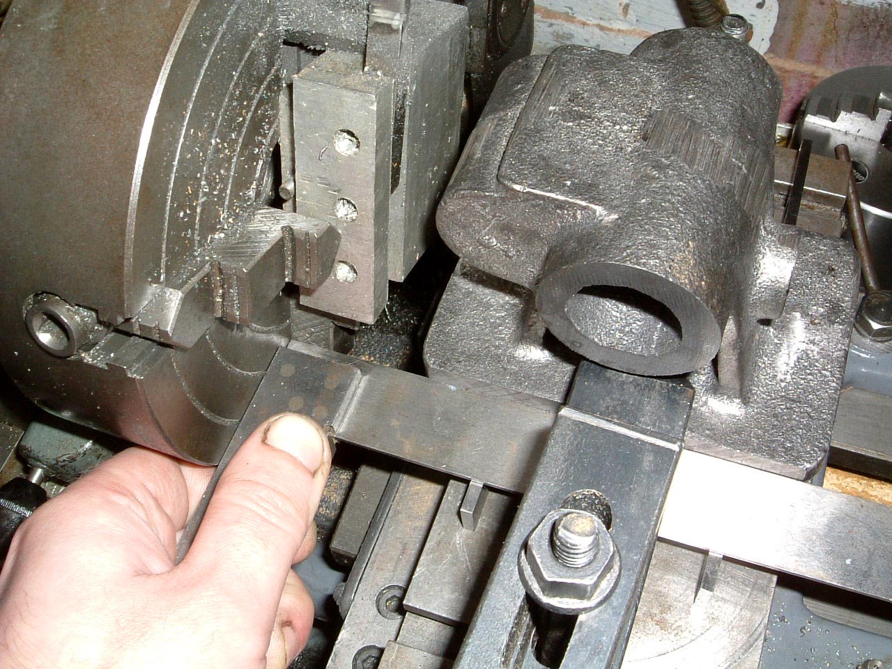
More checks are being carried out to check for rotational errors in the Y axis. It's only possible to check for these once one of the sides has been machined. |
 |
Correcting the Y rotation errors necessitates machining of the side and the front again. |
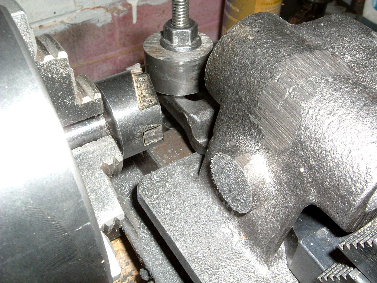 |
The base, front, back, and both sides have been machined square. A small flycutter is being used to face the boss on the side of the casting. |
 |
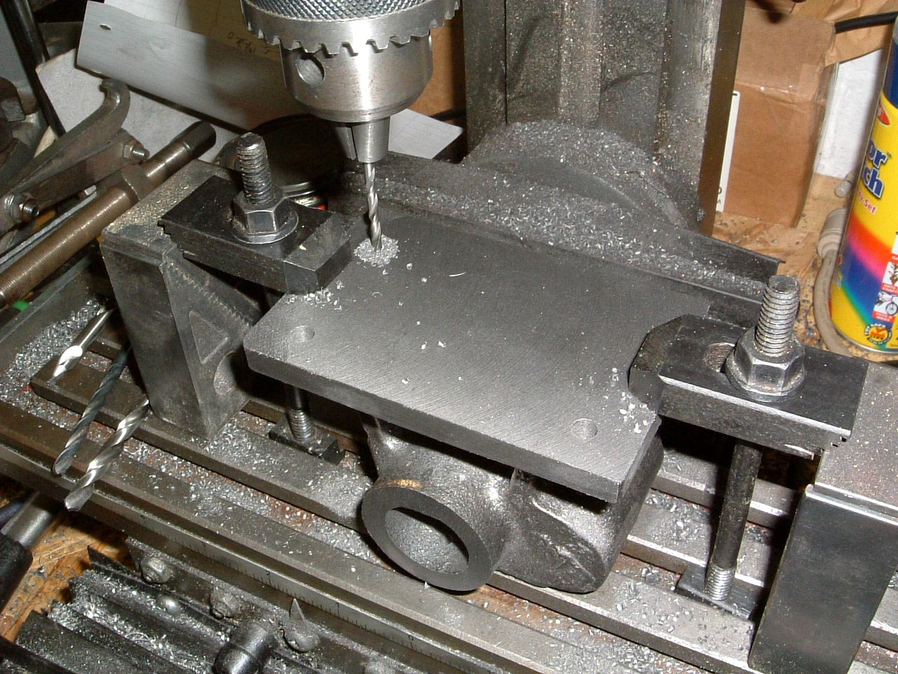
Off the lathe and onto the mini-mill for the final operations on the head casting. The top has been faced off, and a ball nose cutter is being used to tidy up the edge of the faced area. |
 |
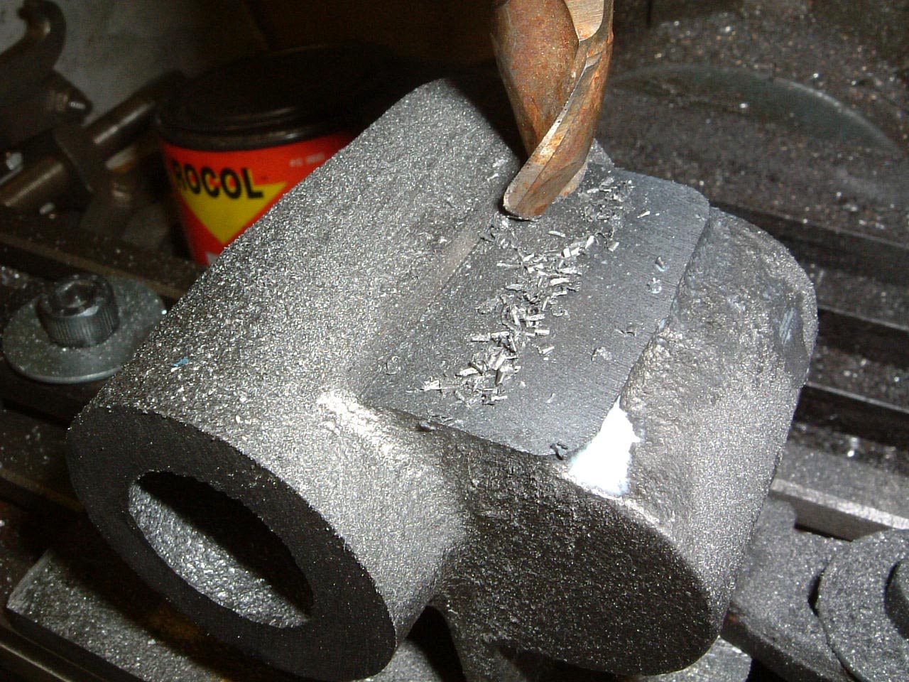
Holes are being drilled for the cotters - my reamers are a bit tapered so I'm using a brand new 3/8" drill to finish the holes off. |
 |
This seems to have worked out well, the cotters are a good slip fit in the holes. |
 |
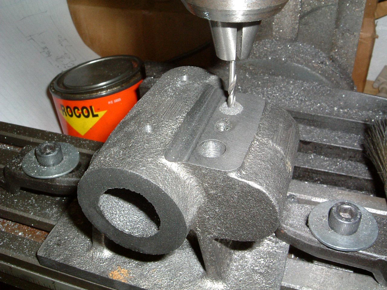
Mounting holes are being drilled 1/4", I'm not going to try and put six holes in there, four will be fine. |
 |
Setting up to drill the hole for the spindle clamp. As above, I'll be using a drill (1/2" this time) to finish the hole, accordinly the brass bar will be turned to fit after the hole has been made. |
| The remaining operations on the head casting, are the boring of the two holes for the spindle and tailstock bar. A between-centres boring bar is going to be needed, and some odd bits and pieces such as a clamp plate to hold the cotters down. | |
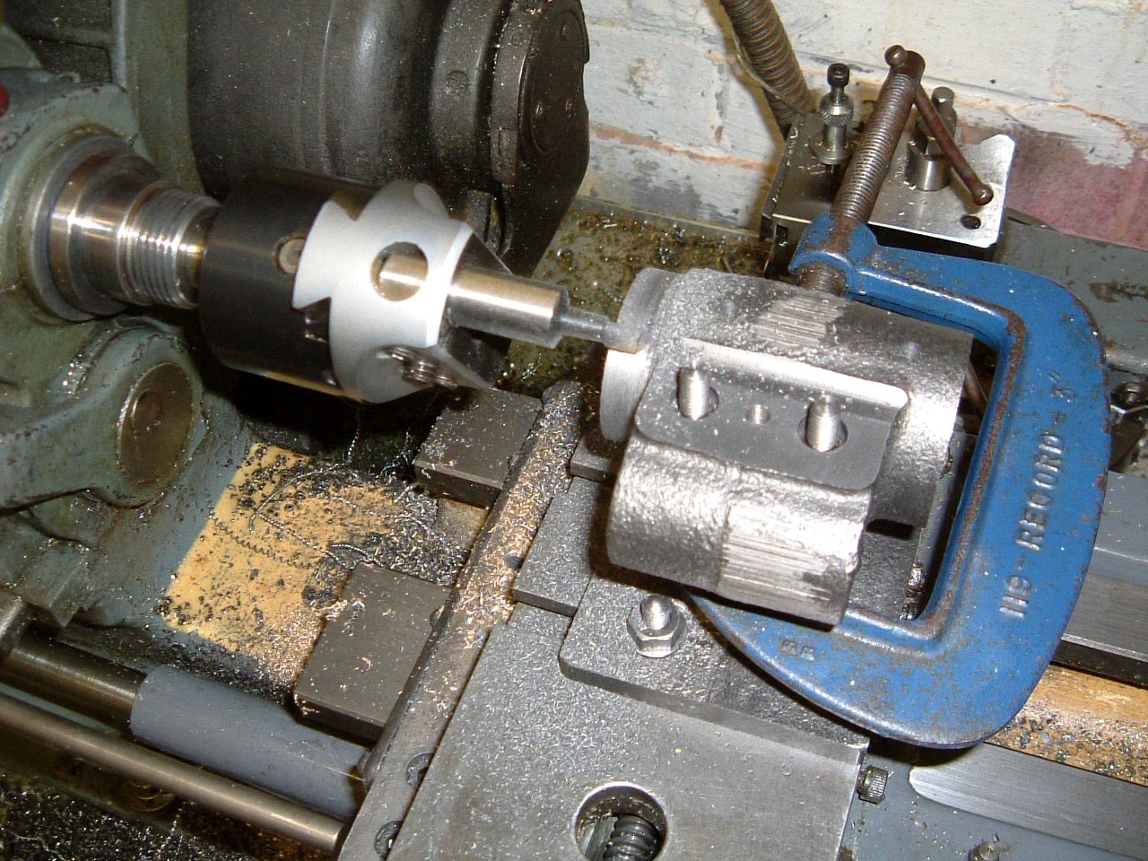 |
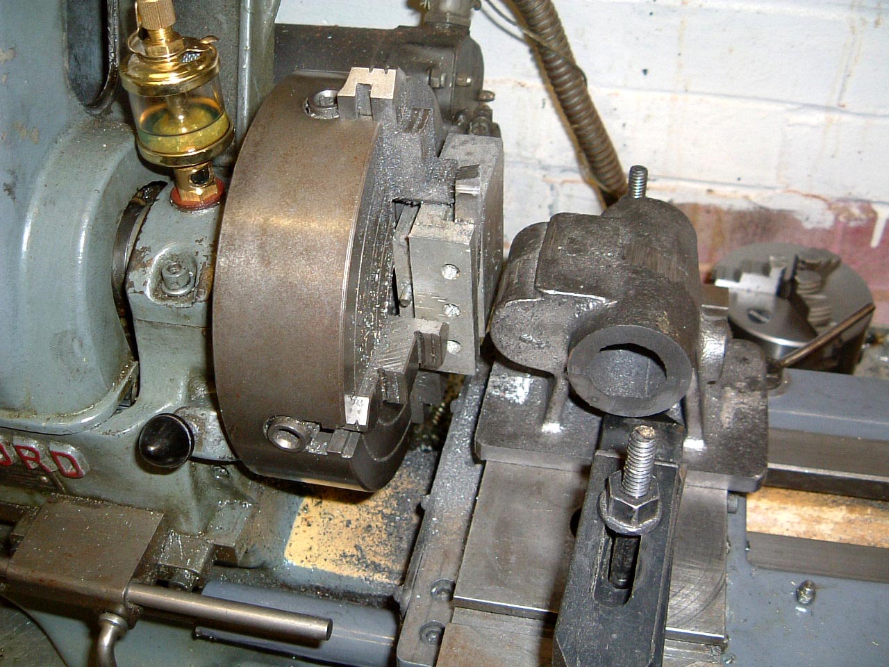
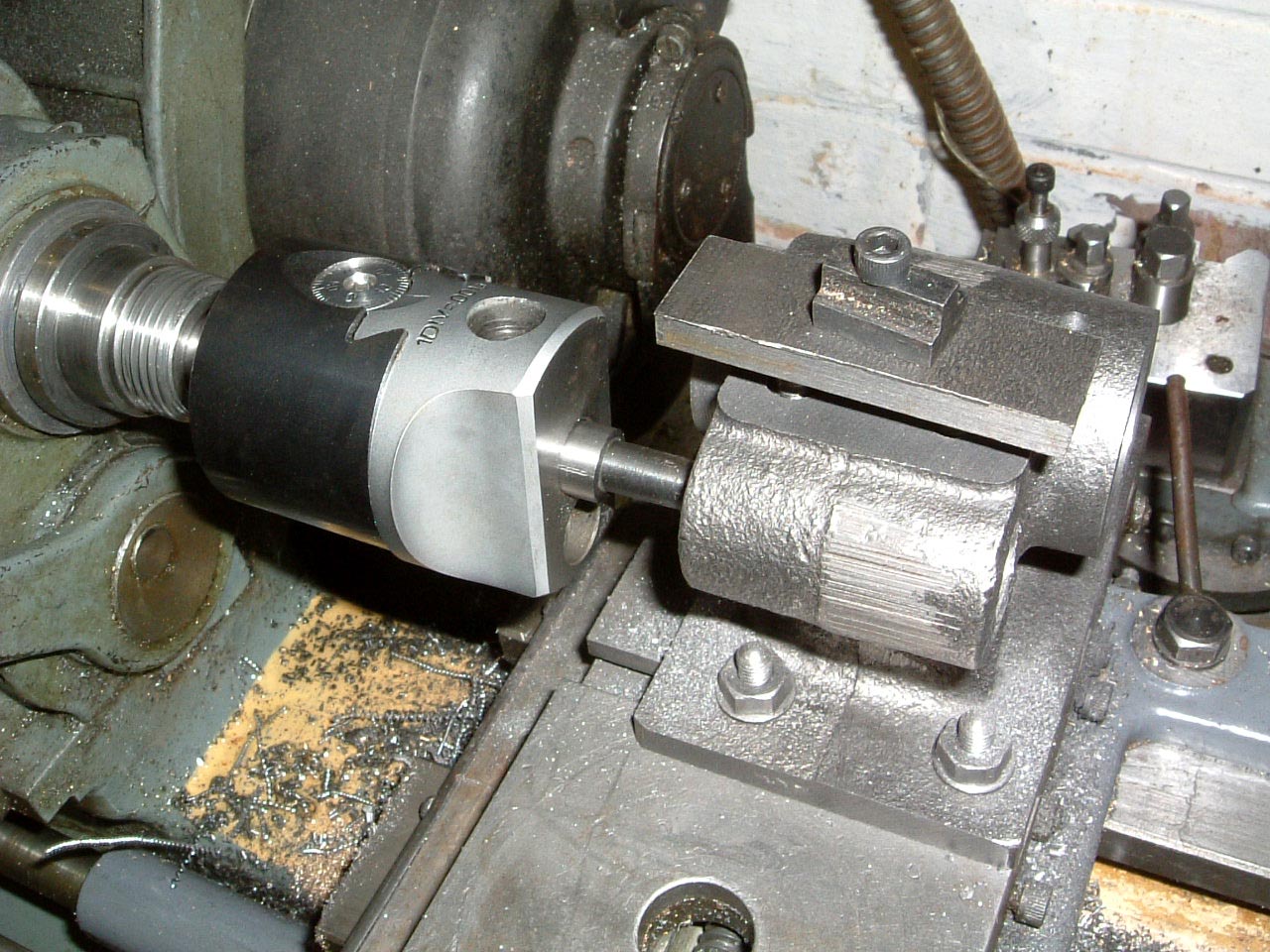
13-Mar-2005: The casting has been mounted on the lathe back to front - it seemed like a better idea to do this, as the spigot can be machined without having to turn the casting round. The boring head is being used with the toolbit turned the wrong way round. As a result of this the lathe is being run backwards, not recommended for any more than light cuts given that the boring head is on a threaded mount. |
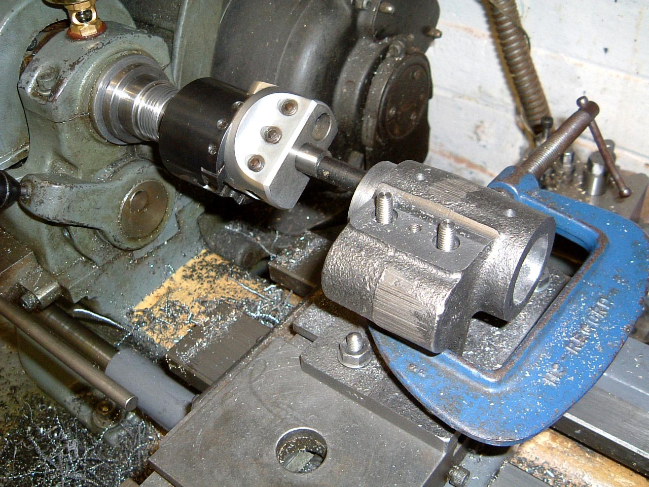 |
The boring head being used in the correct direction, this time to rough out the spindle bore. Due to a small amount of core shift in the casting, this has been bored to 1.080" instead of the 1.0625" bore of the original plans. This is not a problem as the spindle is made to suit. |
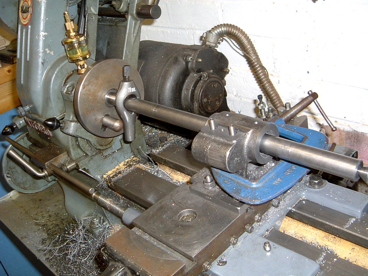 |
Final sizing to 1.085" is made using a between-centres boring bar, a couple of passes were all that was required. |
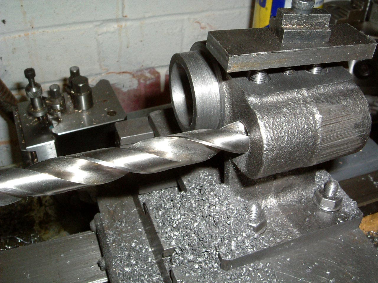 |
Drilling out the bore for the tailstock bar. This is a 1/2" drill bit which will open up the hole enough to take a boring bar. Note the clamp plate over the cotters to stop them moving around. |
 |
Boring out to 0.622", a reamer will be used to take of the last few thou and get the bore parallel. The fit turned out OK, and not loose as I expected. |
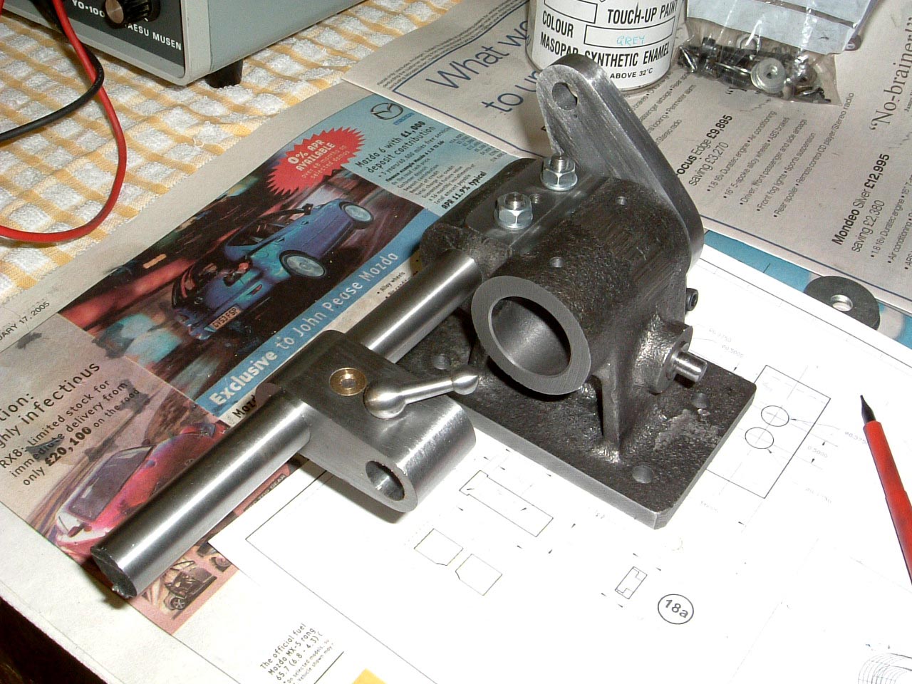 |
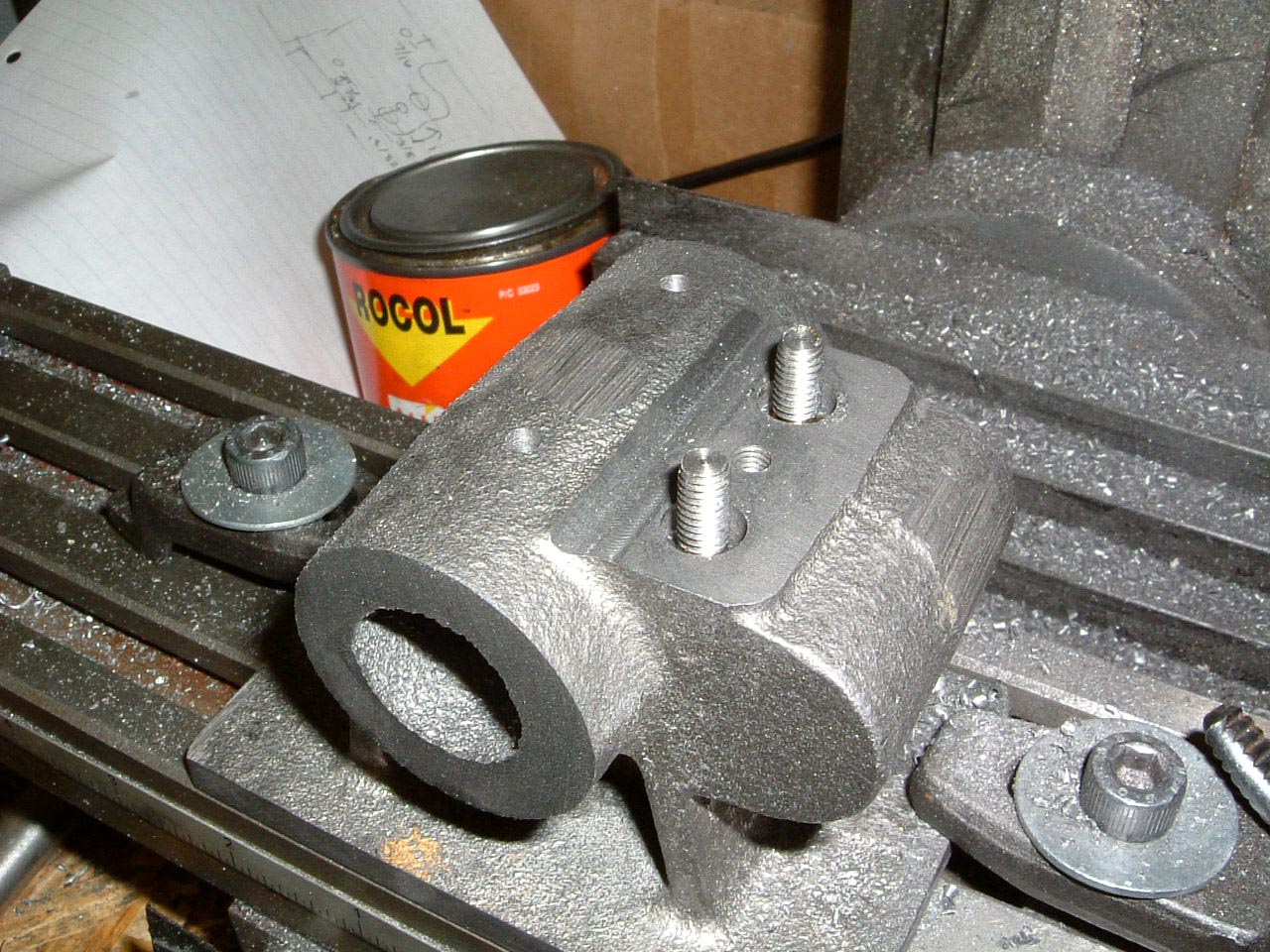
That's it for now - the spindle clamp has been split and threaded, then assembled into the head casting. The next chunk of work will concentrate on finishing the basic head. |
These pages are maintained by Duncan
Munro. All content on this site is Copyright ©2002-2025 Duncan
Amplification.
Warning: These pages consist of images and descriptions of equipment
which can reach high temperatures creating hazardous and potentially dangerous
situations. These pages should not be taken as a step by step guide on how
to construct any items or carry out any particular procedure, nor should any
references to safety contained herein be taken to guarantee safety in all
situations.