|
|
VDH - Basic head Last updated: 30 Nov 2016 |
Now the head casting has been sorted out, the remaining parts can be made to complete the basic head. In this state, the head can still not be put to useful work, as the indexing gear needs to have 24 holes drilled in it. I'll leave the drilling of the gear until later, rather than rush it for no good reason.
The spindle
This worries me more than any other part on the head - it has to be a good fit in the bore of the head casting, without being tight. There's a fair weight of metal has to come off this bar - a time consuming operation, and machining an extra 'thou' or two more than planned will render it useless...
 |
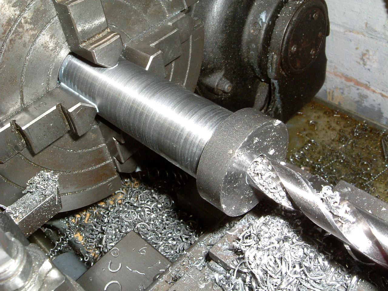
14-Mar-2005: Starting off the spindle, the back face has been skimmed. GHT suggests centre drilling the back face, although I'm drilling it half way through as the spindle is over 4" in length and drilling in one hit from the other side will be a bit of a chore. |
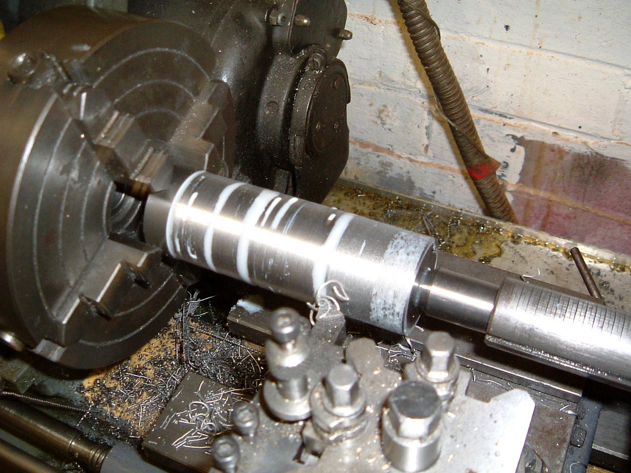 |
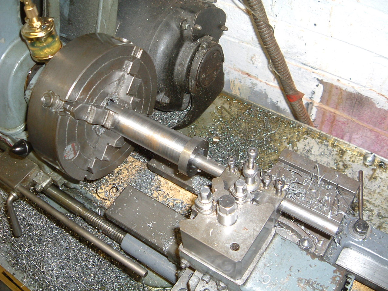
With a centre for support, the spindle is being roughed down to 1.125" diameter. I did spend some time recently truing up the lathe bed, and correcting the tailstock offset which seems to have paid off. Checking in five places along the bar with the digi-caliper gives identical readings of 1.1245". This is, of course, pushing the repeatability and accuracy of the caliper somewhat. |
 |
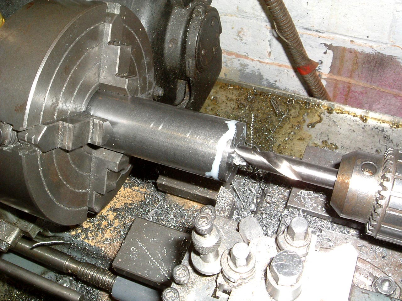
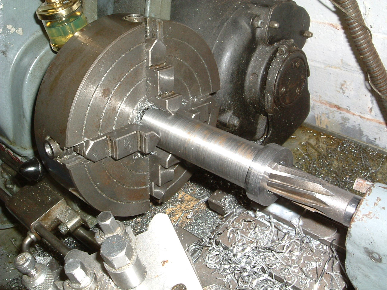
Turned round and re-centred in the 4 jaw chuck, it's being drilled through from the front. The job is made a lot easier by previously drilling from the back. This is about as much as I can do for now as I don't have a boring bar long enough to do the length of the spindle... |
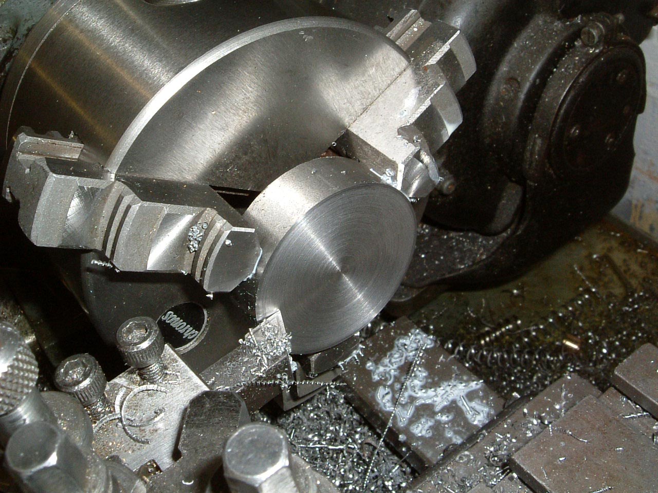 |
17-Mar-2005: The thrust nuts are being made while I'm waiting for some extra tooling to turn up. Both faces of the nut have to be parallel, this being especially important for the nut with the larger hole which takes up any axial play in the spindle. One end of the bar section is being faced. |
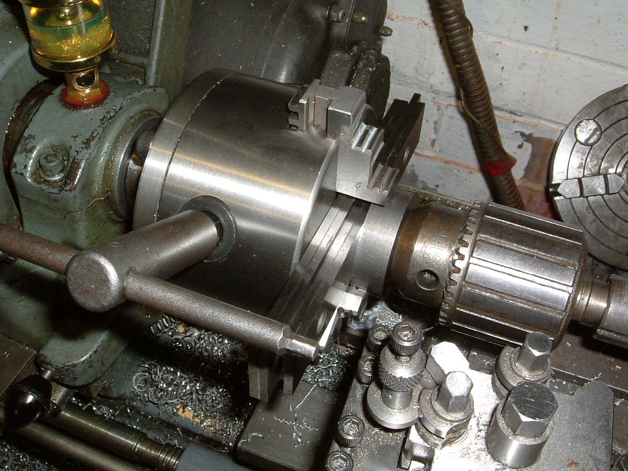 |
The bar is turned round, and parallels are used to get the back square to the axis of the lathe, the chuck is giving a 'push' to the bar to ensure it's tight against the parallels. This method did not prove satisfactory, so I used a couple of smaller parallels 'end on' which gave much better results. |
 |
Once the nut blank is squared up, it's simply a case of trimming the thickness and boring/threading. |
 |
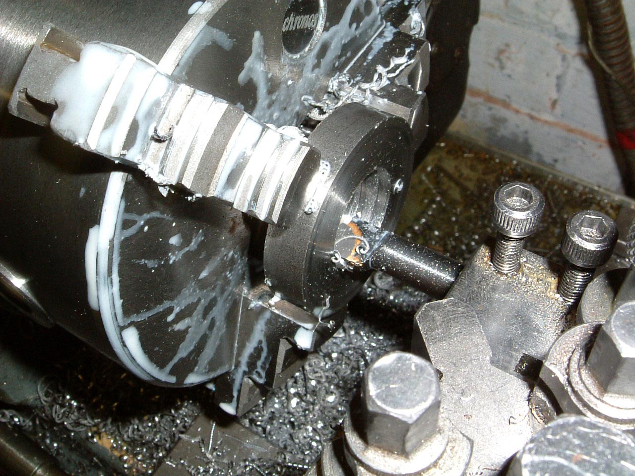
18-Mar-2005: The blacksmiths drills and 3/4" machine reamer have arrived, the homemade long 1/2" boring bar has been made. Just machining the spindle out to 0.746", a task which took a couple of hours as the extra length boring bar can only take 0.005" off at a time without 'squeaking'. |
 |
Finishing to 0.751" with the machine reamer, quite impressed with this - the shank looks like it's forged/rolled, the first 3/4" is definitely solid carbide (and suprisingly it's British). A bargain at £16 from Tracy Tools. If you need reamers, taps, or drills give them a shout. |
 |
20-Mar-2005: The kit contains material to make the mandrel on which the spindle is mounted for final turning. This ensures that the centres are concentric on the spindle. |
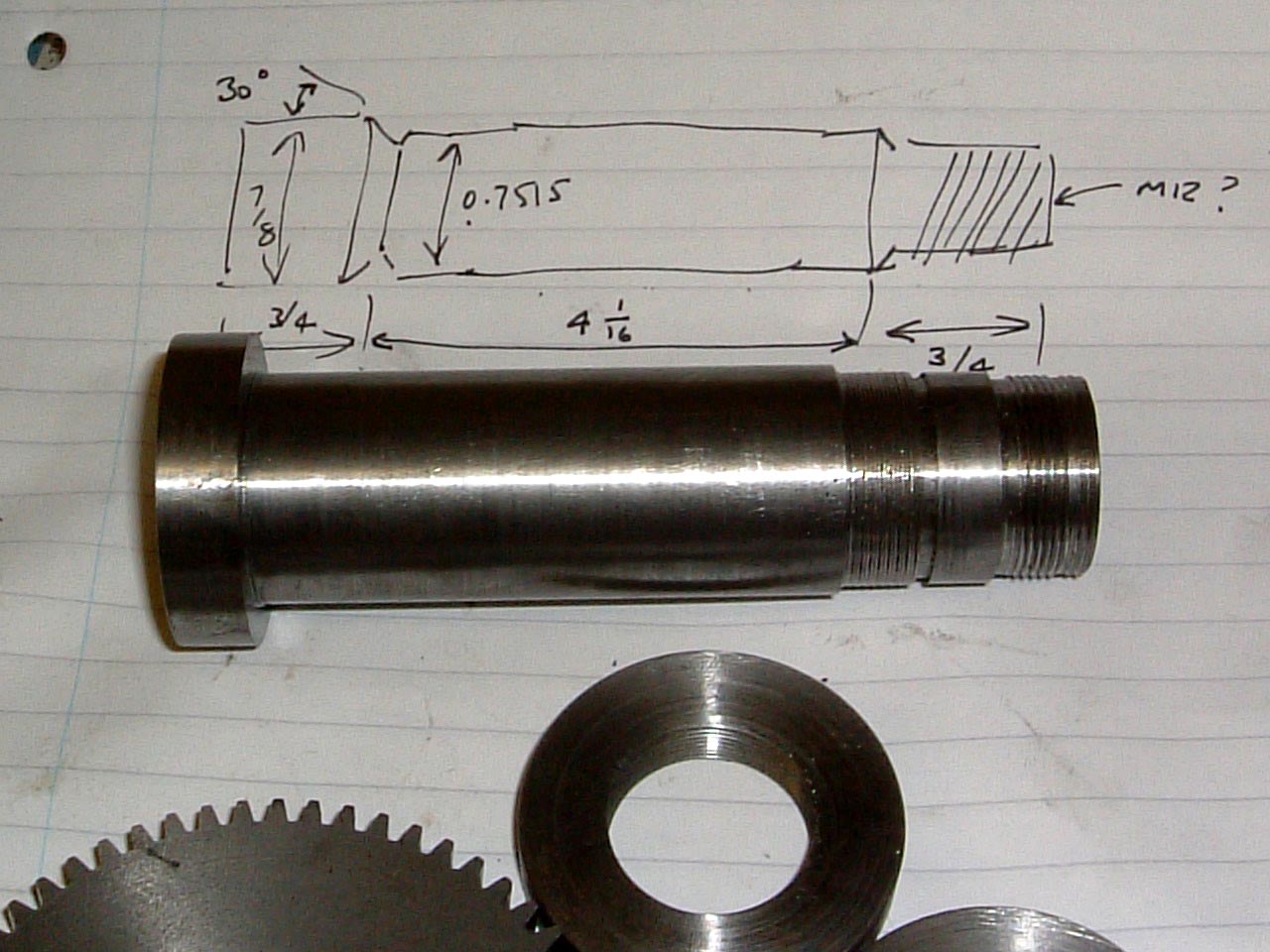 |
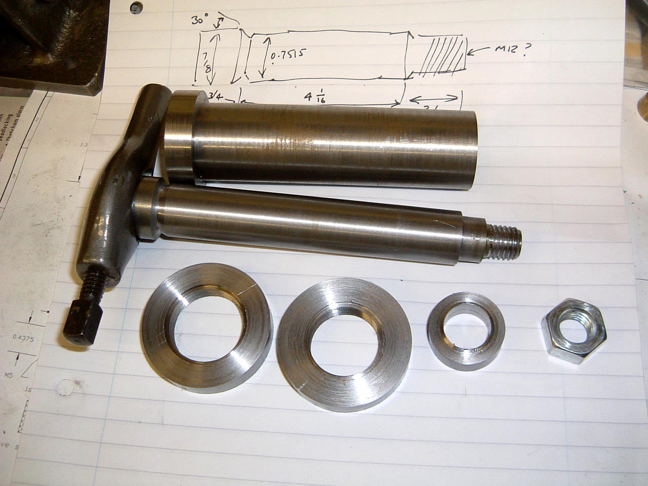
The almost finished spindle - a keyway will need to be cut in it for positively locating the large gear, and the nuts need to be tapped for clamping screws. |
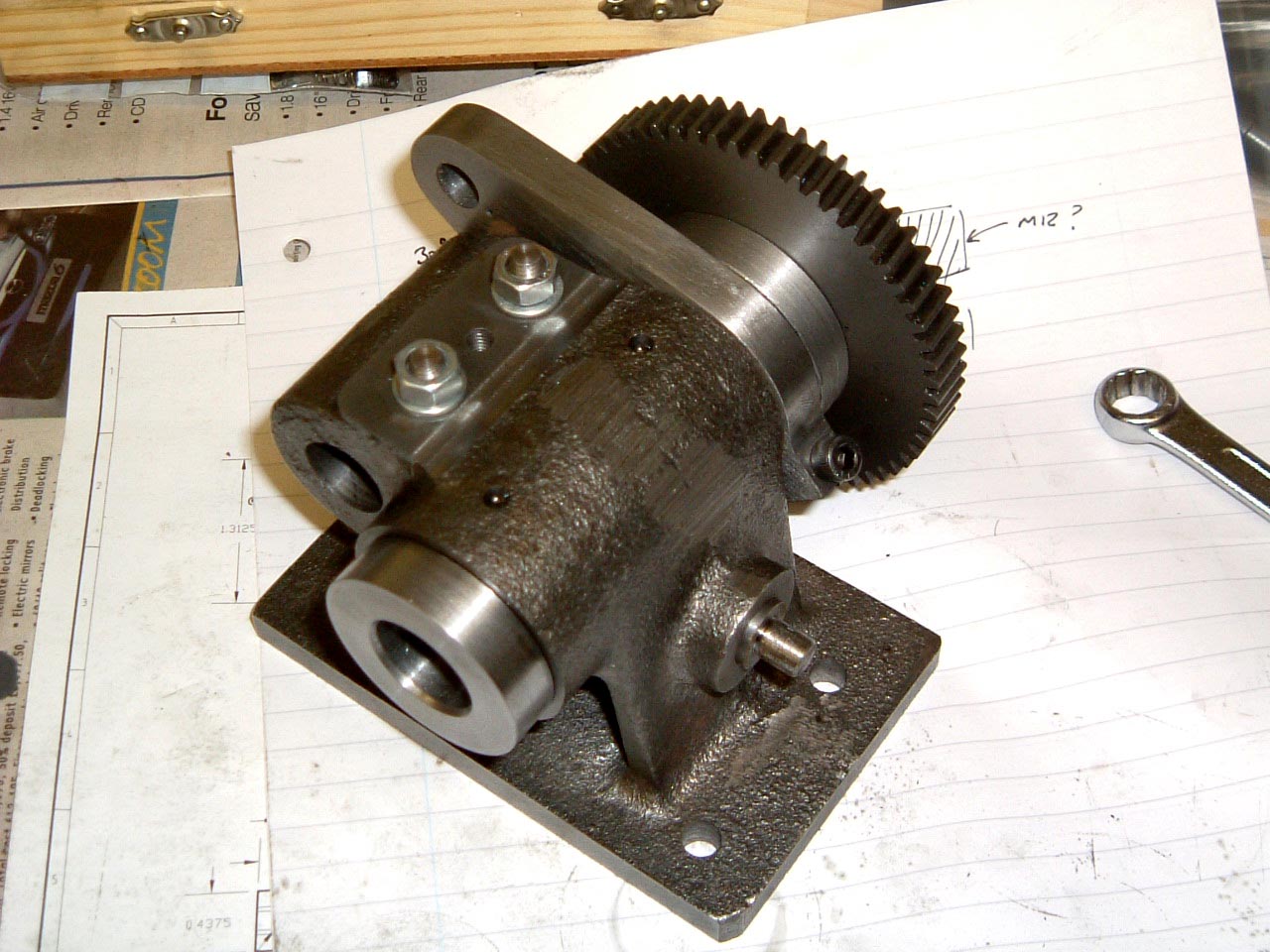 |
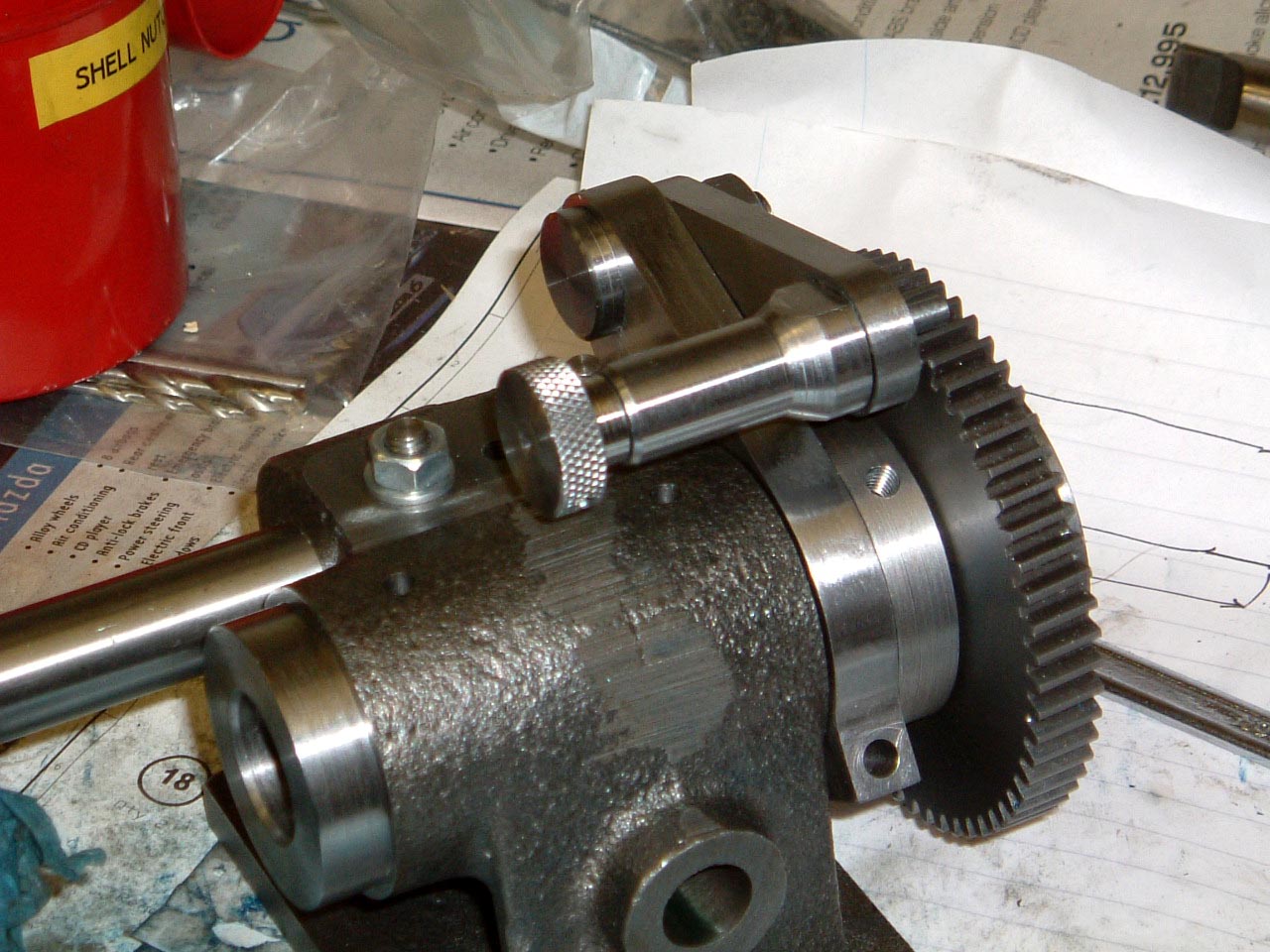
Temporarily assembled, it's all starting to look like a dividing head. Everything fits well, which is something of a relief... |
 |
24-Mar-2005: The front face has been blued up, and not a trace of dye being scraped off due to the spindle riding on the chamfer. The spindle was undercut slightly and the front face scraped in, followed by the back face. |
Other items
 |
25-Mar-2005: These were fairly uneventful, no problems encountered. Just need a ball handle now, and this section is finished - the 24 holes in the gear and the three holes in the spindle come later when more of the dividing head has been built. |
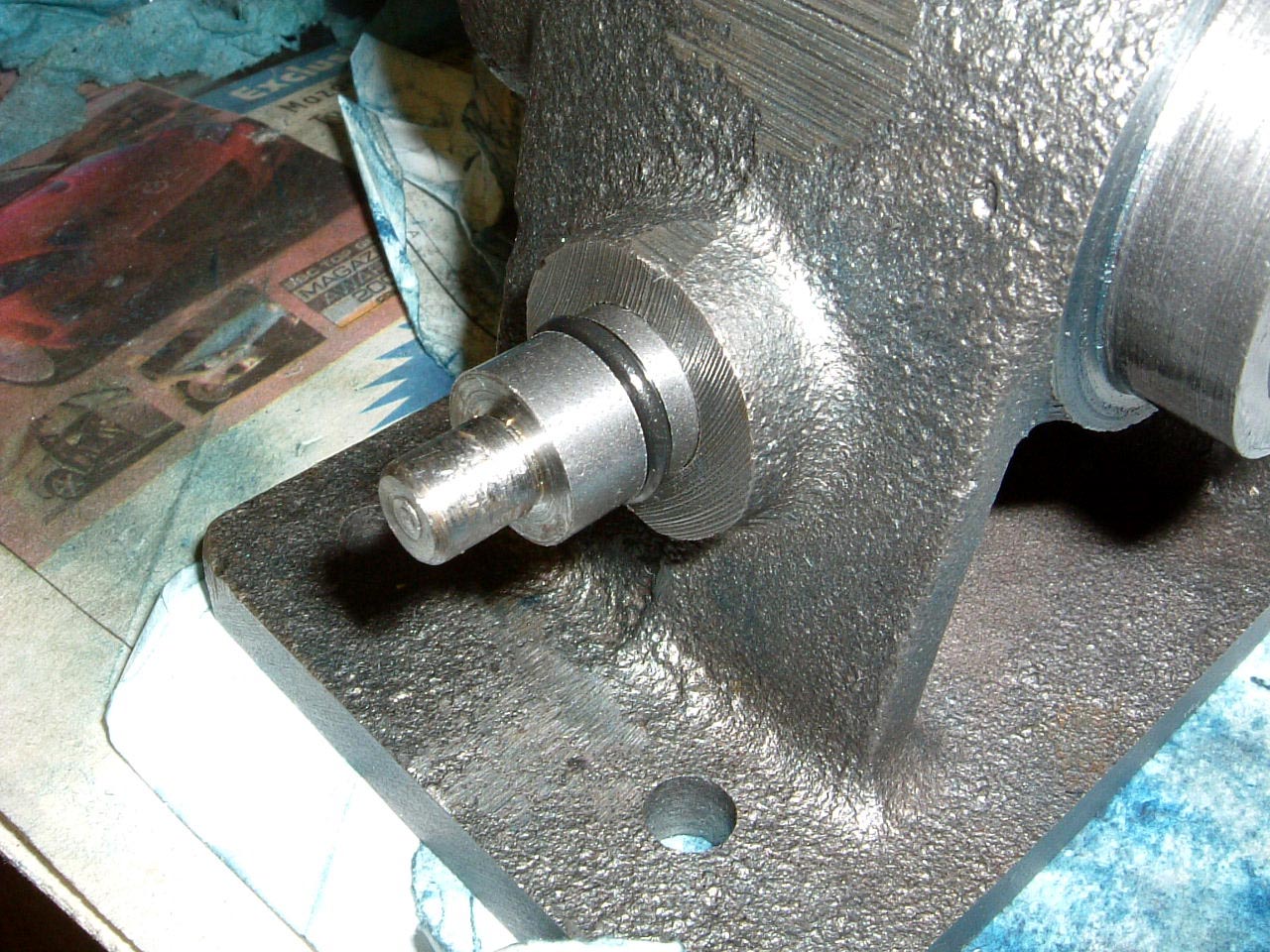 |
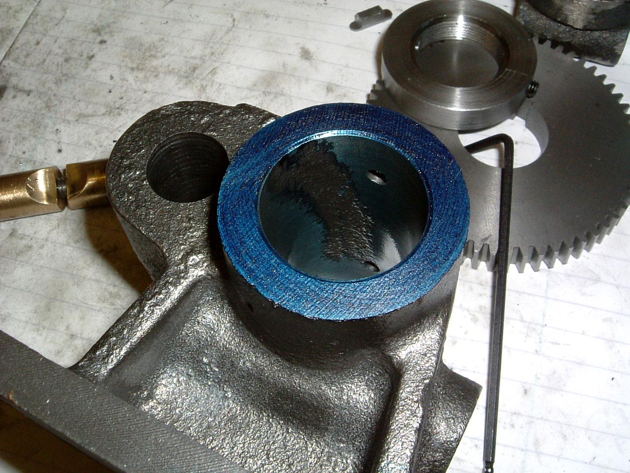
27-Mar-2005: Here's a small modification. Any excess of oil in the dividing head will migrate to the well in which the spindle clamp lives. This will eventually drip out of the hole in the side and look untidy. A groove has been machined for an 'O' ring, which serves the dual purpose of keeping oil in, and adding a little friction to prevent the lever from flapping around. |
These pages are maintained by Duncan
Munro. All content on this site is Copyright ©2002-2025 Duncan
Amplification.
Warning: These pages consist of images and descriptions of equipment
which can reach high temperatures creating hazardous and potentially dangerous
situations. These pages should not be taken as a step by step guide on how
to construct any items or carry out any particular procedure, nor should any
references to safety contained herein be taken to guarantee safety in all
situations.