|
Home
Up
|
For this section, the dividing head will be expanded to allow indexing from
pre-drilled plates. The whole situation is still 'chicken and egg', because
the micro-attachment is required to drill the plates, which are are required to
drill the main gear, etc. etc.
Worm bracket
 |
28-Mar-2005: Nothing special about this one although I did manage
to screw up machining the cylindrical surface. I will remind myself in future that
1-5/8" is definitely not 1.5625" and will use the calculator to turn fractions into
real numbers... |
 |
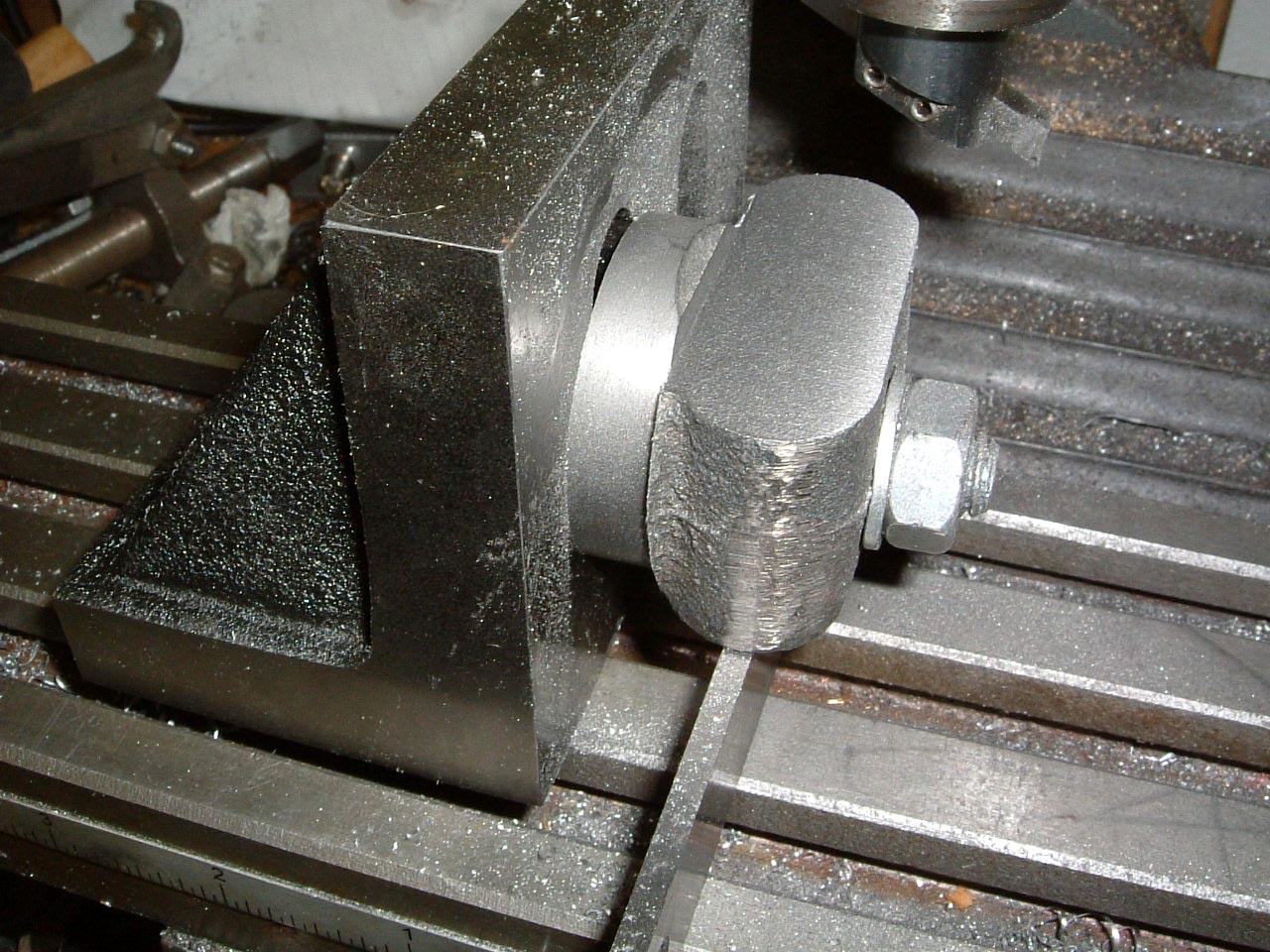
The part machined casting is now in the milling machine to get some
of the flat surfaces machined. The mill will also be used to bore/ream
the 3/8" diameter holes in the casting. |
Worm and Sleeve
 |
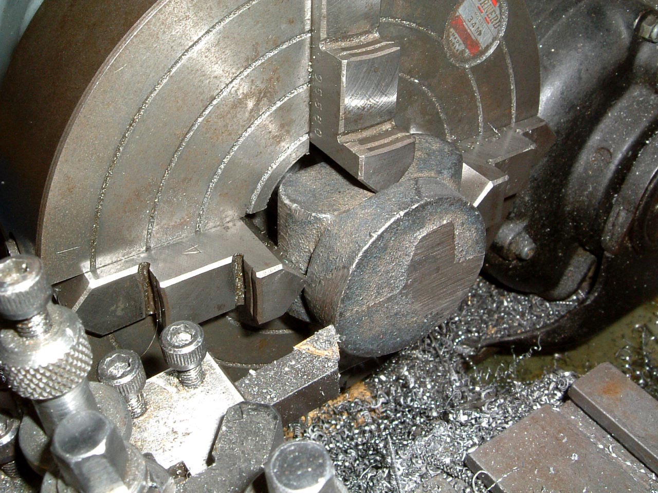
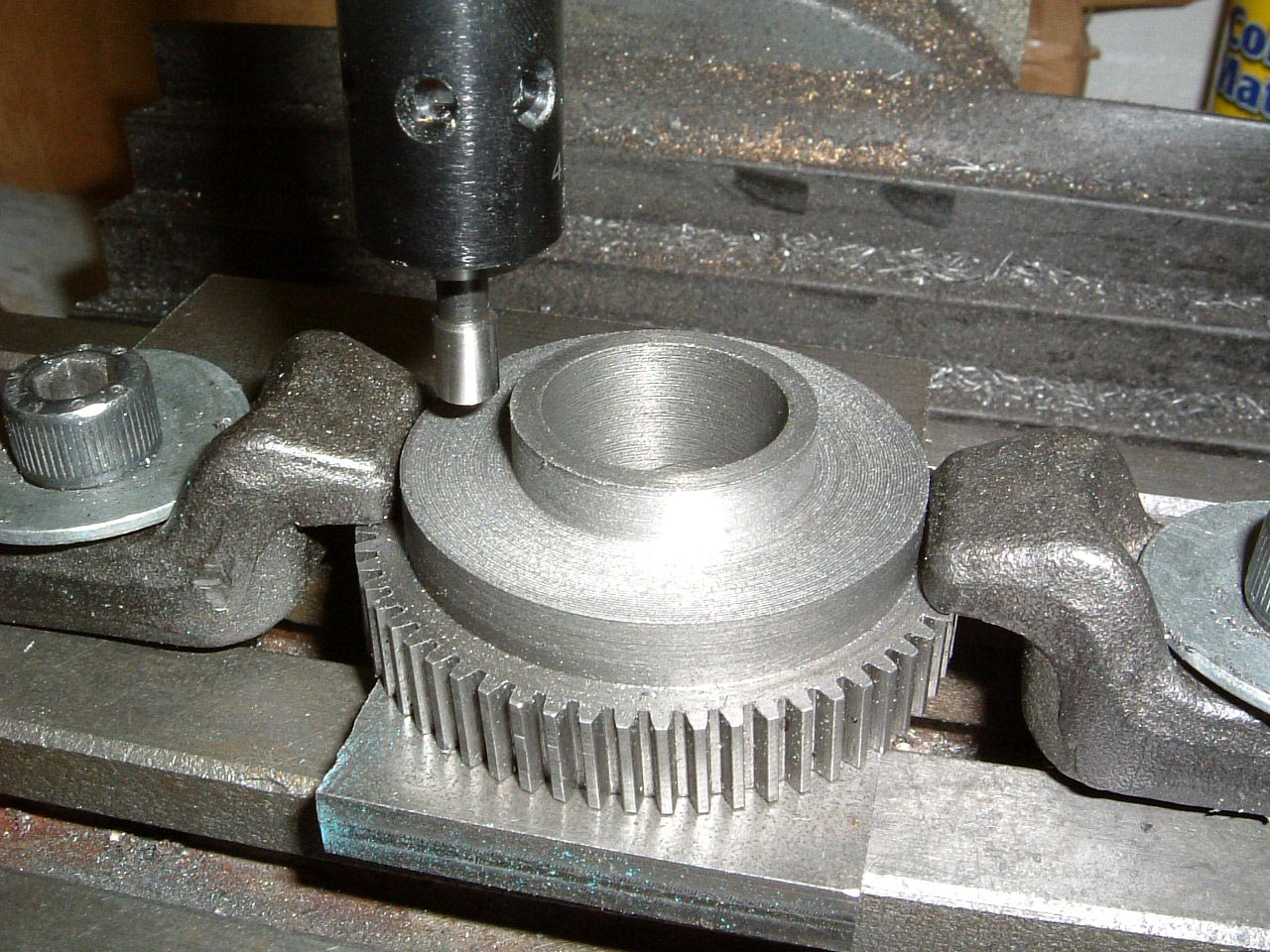
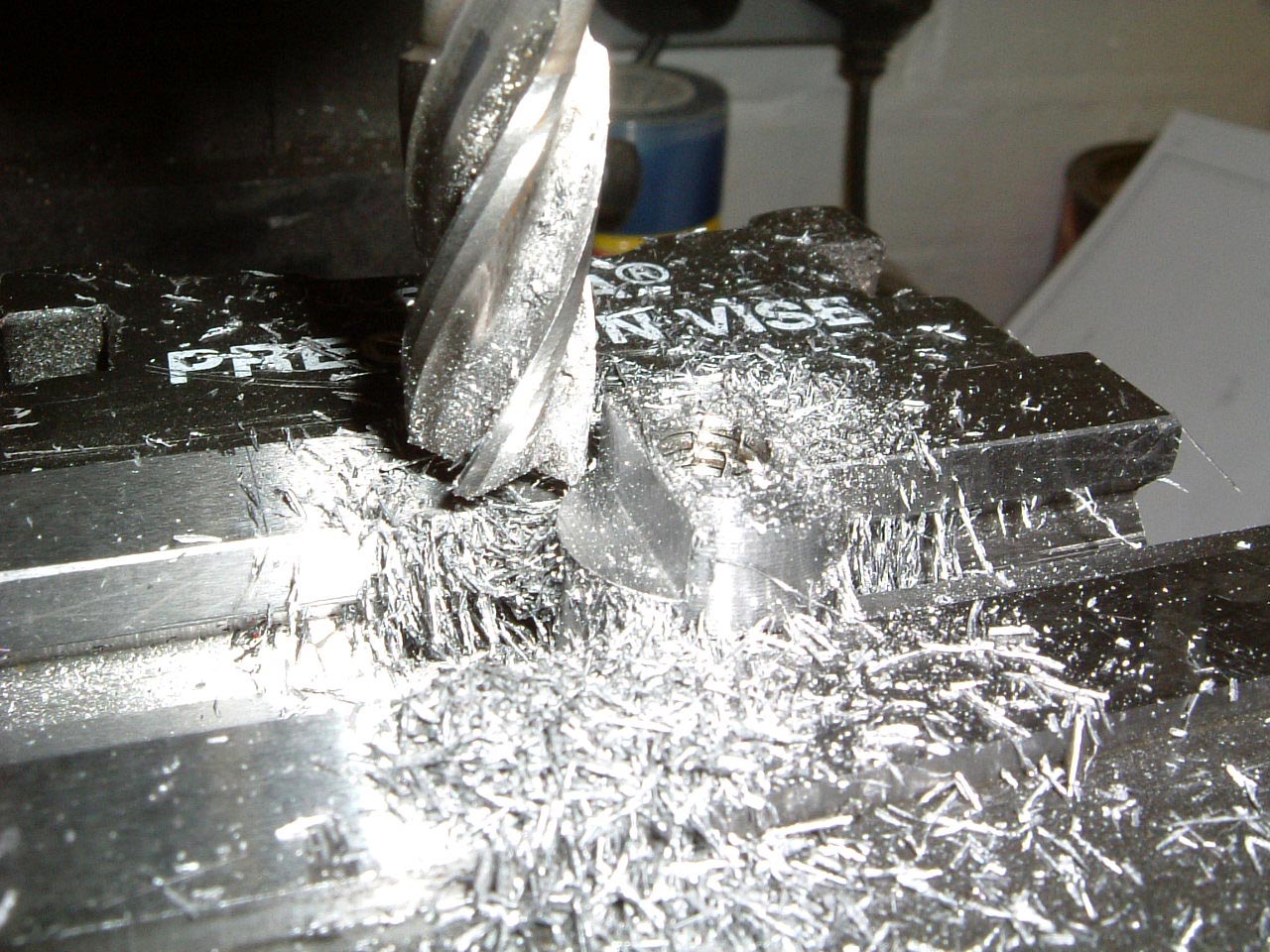
03-Apr-2005: This is the method used in the book to get the boss
on the sleeve to stand proud of the gear by 0.001". The cutting tool
is brought up to the gear and wound back by 0.001", after which it is
retracted and the gear removed to allow the shoulder to be machined to
the right size. |
 |
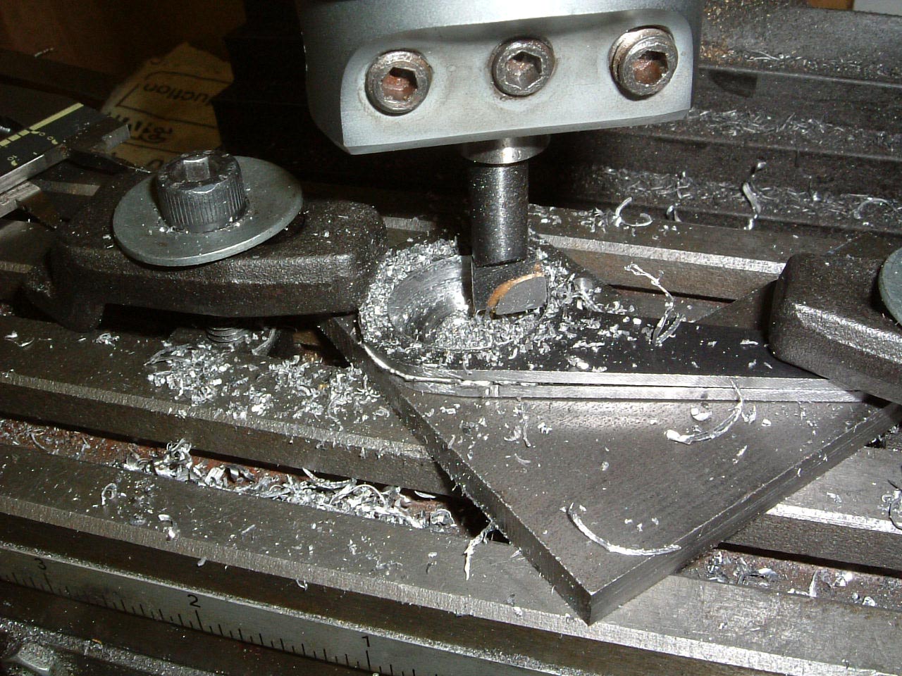
I'm just using an endmill here to machine the relief for the bolt hole. |
 |
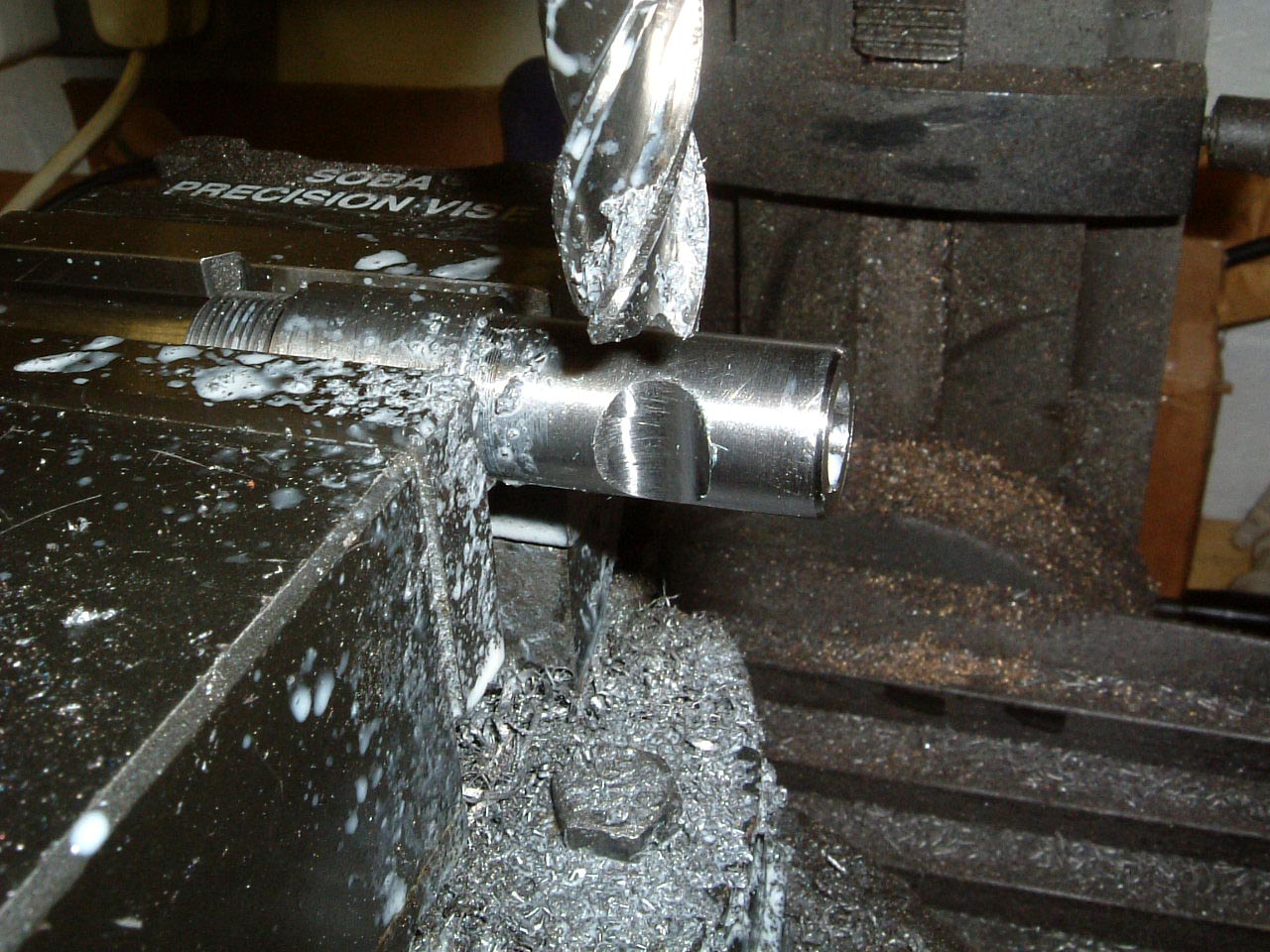
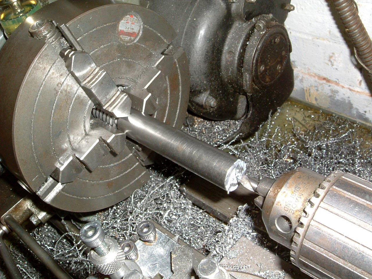
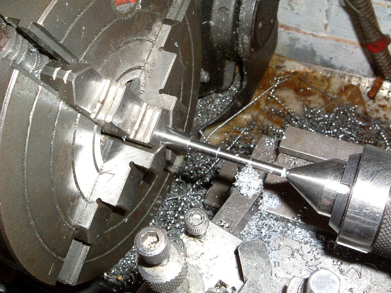
The worm comes pre-machined which saves quite a bit of setup time. A centre
hole is being made on the end of the bar after which the bar will be mounted
between centres. |
 |
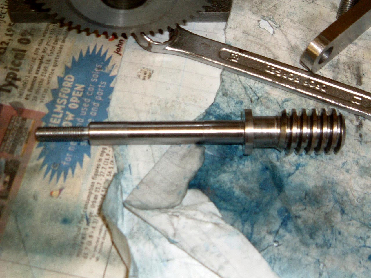
The finished worm ready to have the fit checked. |
 |
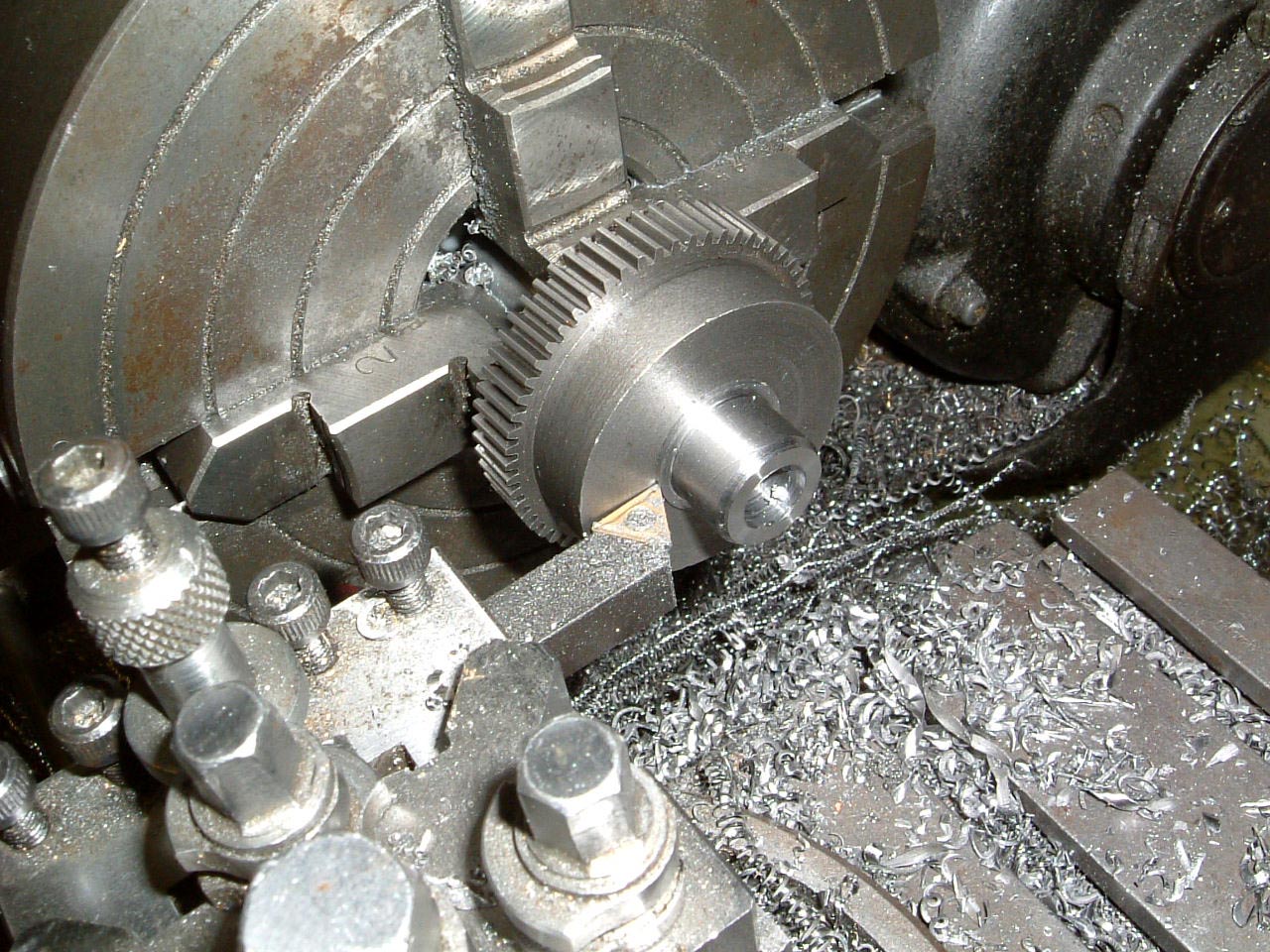
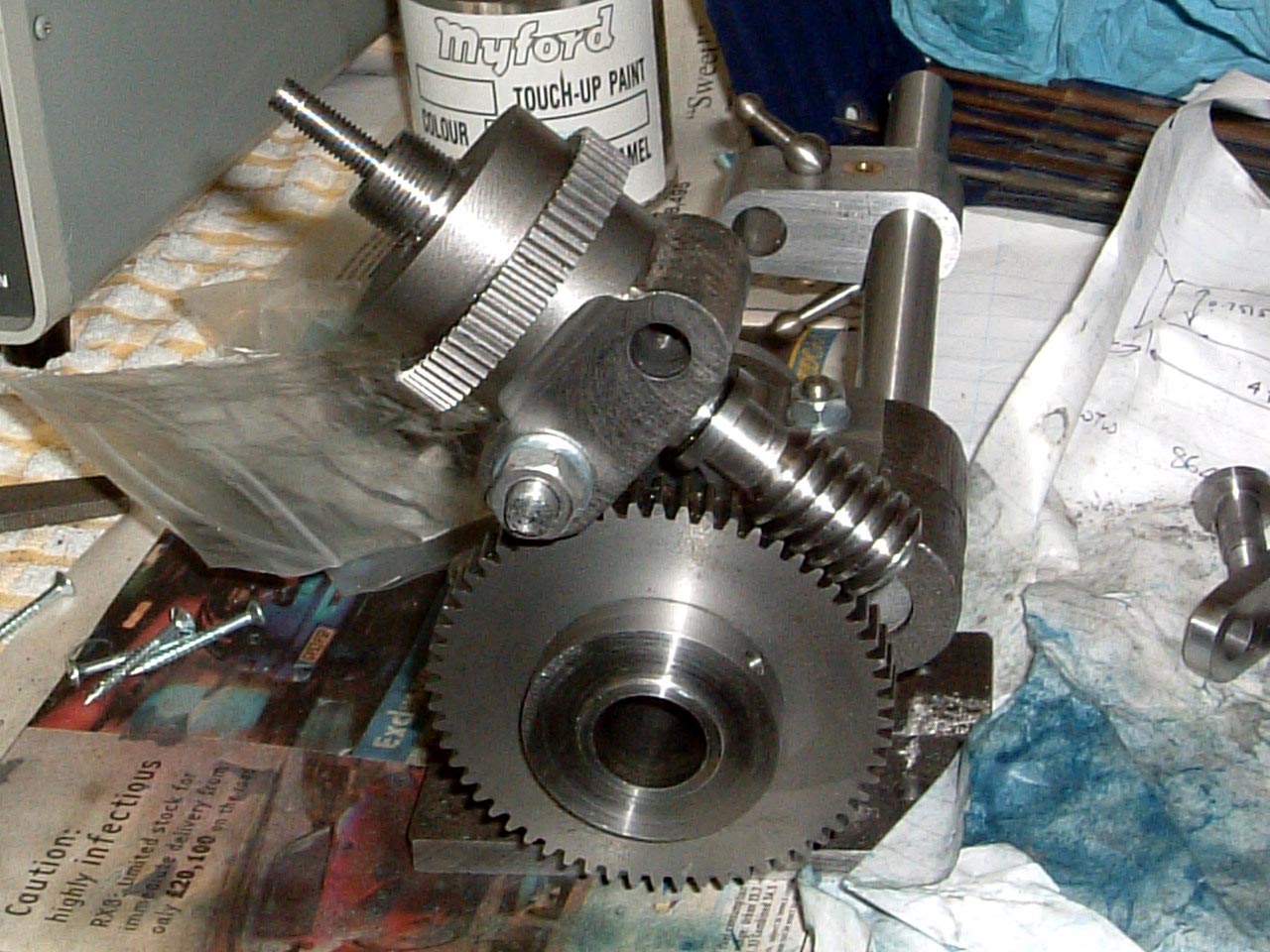
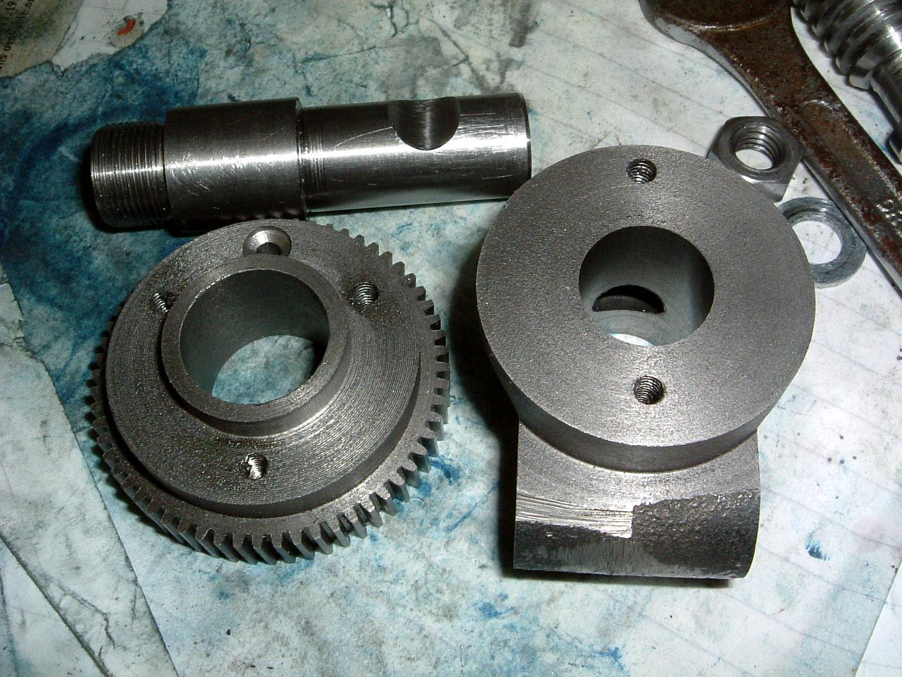
The worm, sleeve, and gear all installed in the worm bracket. Everything
turns smoothly so I'm quite pleased. |
Micro worm wheel
 |
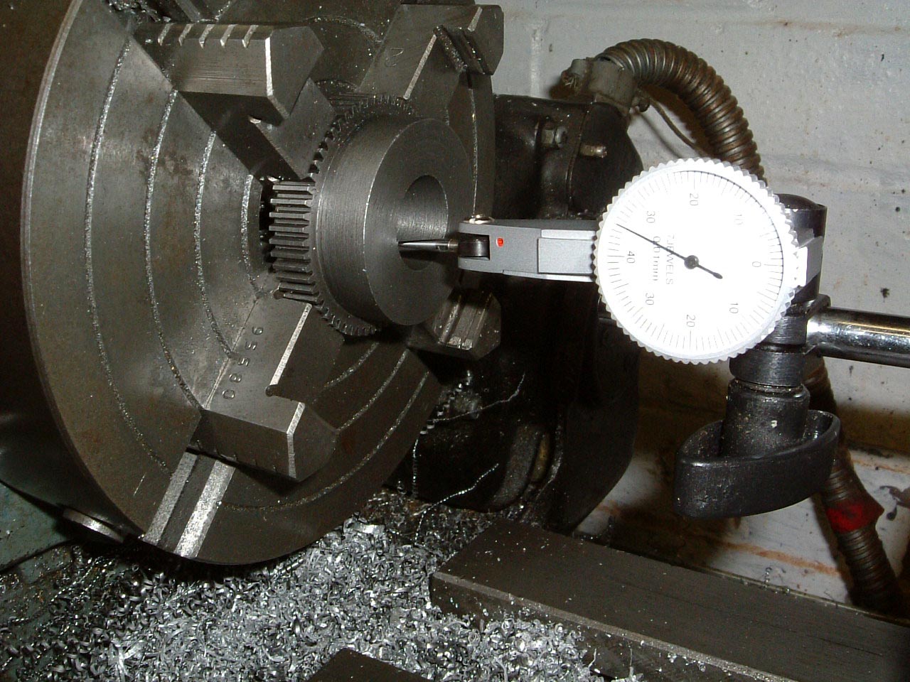
08-Apr-2005: This arrives in part machined condition, a recess for
mounting the plates needs to be machined and a handful of holes to secure the plates.
Here it's being "clocked" to ensure that the recess is machined concentric
with the bore. |
 |
09-Apr-2005: Something of an experiment going on here... Thomas
describes the use of a jig in his book to drill the holes for retaining the
plates, but I'm trying an alternative method
of using the X/Y wheels on the mill to move from the centre of the bore. |
 |
It worked out well, although the worm bracket (using the same method)
had the hole 0.100" out of place as I forgot to subtract half the width
of the centre... Another hole has been drilled and tapped on the other
side, so the plates will have their "12 o'clock" position 180 degrees out from
where they would normally have been. |
Sector arms
 |
09-Apr-2005: A paper template is being used to get the shape right
for the sector arms. The strip of steel supplied with the kit has been
cut into two sections, and bolted together through both the handle holes and the
centre. A slitting saw has been used to get the initial shape of the
straight edges. |
 |
Cut to shape, and now in the process of being filed. It didn't work too
well on the circular areas, it would have been an idea to make up some 'filing buttons' from some
thicker steel material to get a really nice profile on this part. |
 |
The 0.950" bore is being machined on the mini-mill with both strips of steel
being machined at the same time. I did initially try
this in the lathe but the whole lot moved on the faceplate, so the clamping
arrangement I used was not too good... |
 |
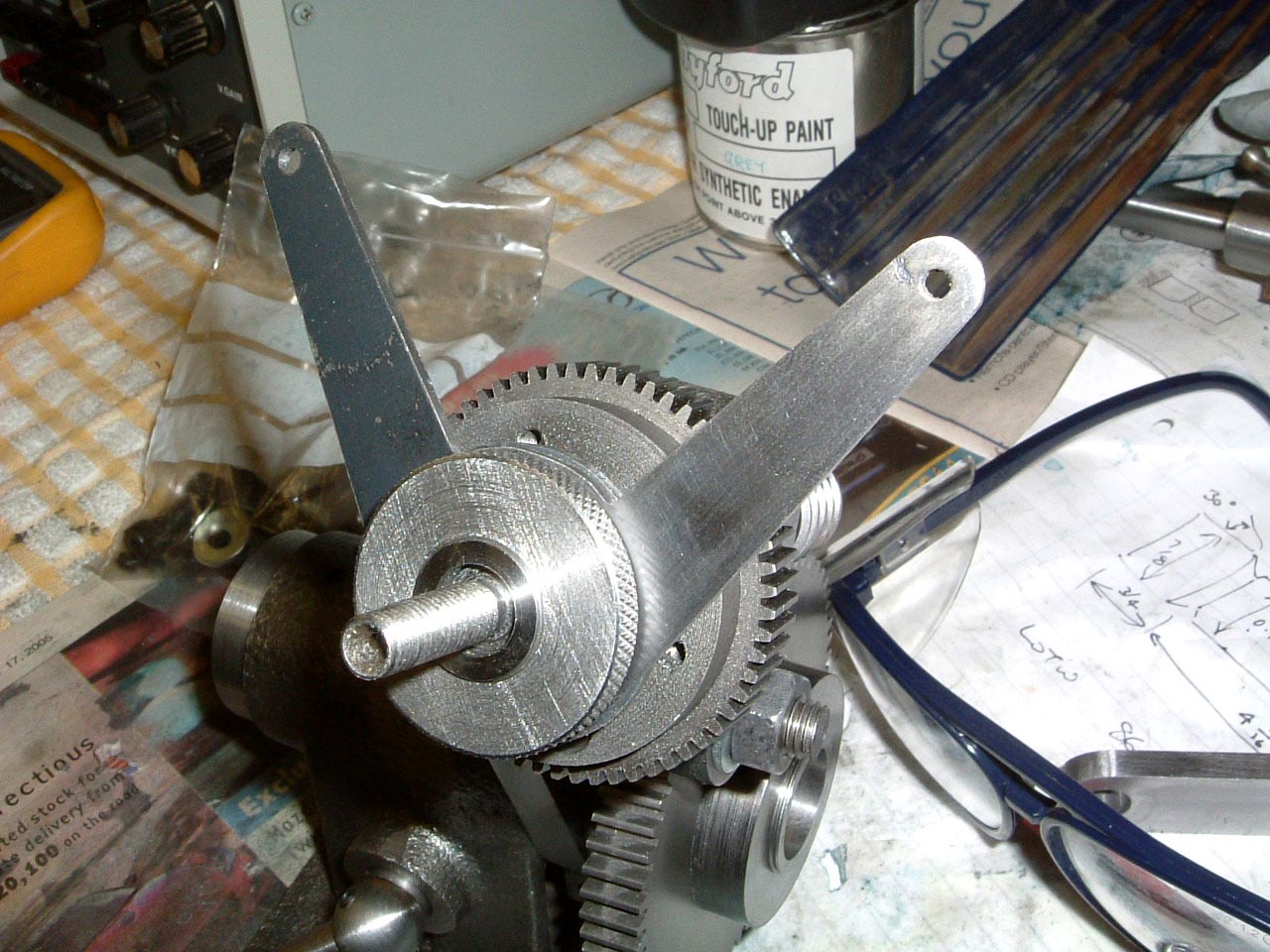
A trial fit on the machine, it does look a bit better than I feared it
might. Next, there are a couple of parts to make up to clamp the
sector arms together. |
Plunger
 |
14-May-2005: This is the nut on which the plunger arm sits, would have
been easier with a dividing head and it didn't turn out too well. It will
do the job for now, but will eventually have to be re-made. |
 |
This has to be the worst bit - machining the silver steel plunger. I
didn't do a very good job of making this, the operation is sticky and there
are concentricity errors - another one which will do for now, but will have to
be re-made. |
Making the 60 hole plate
 |
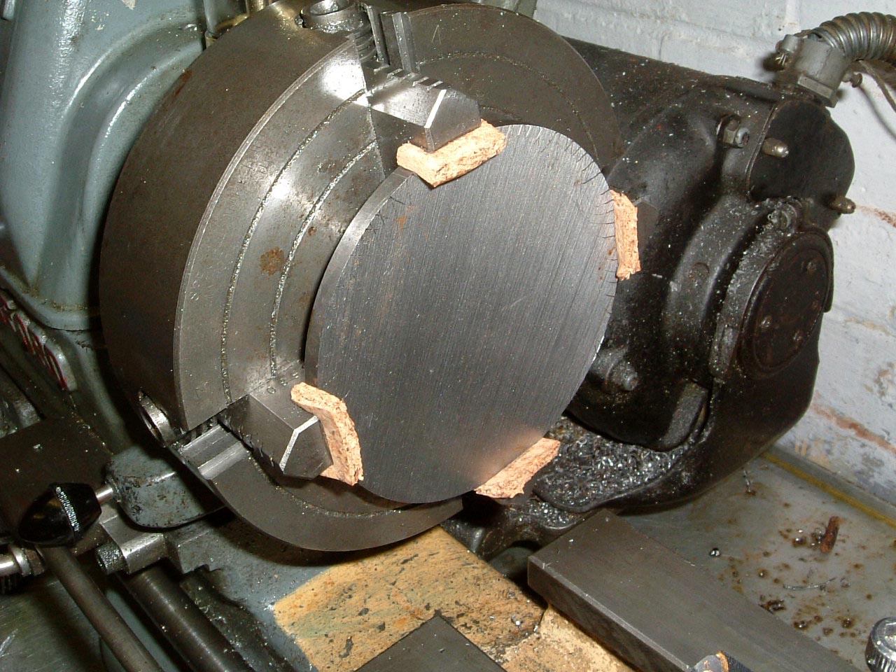
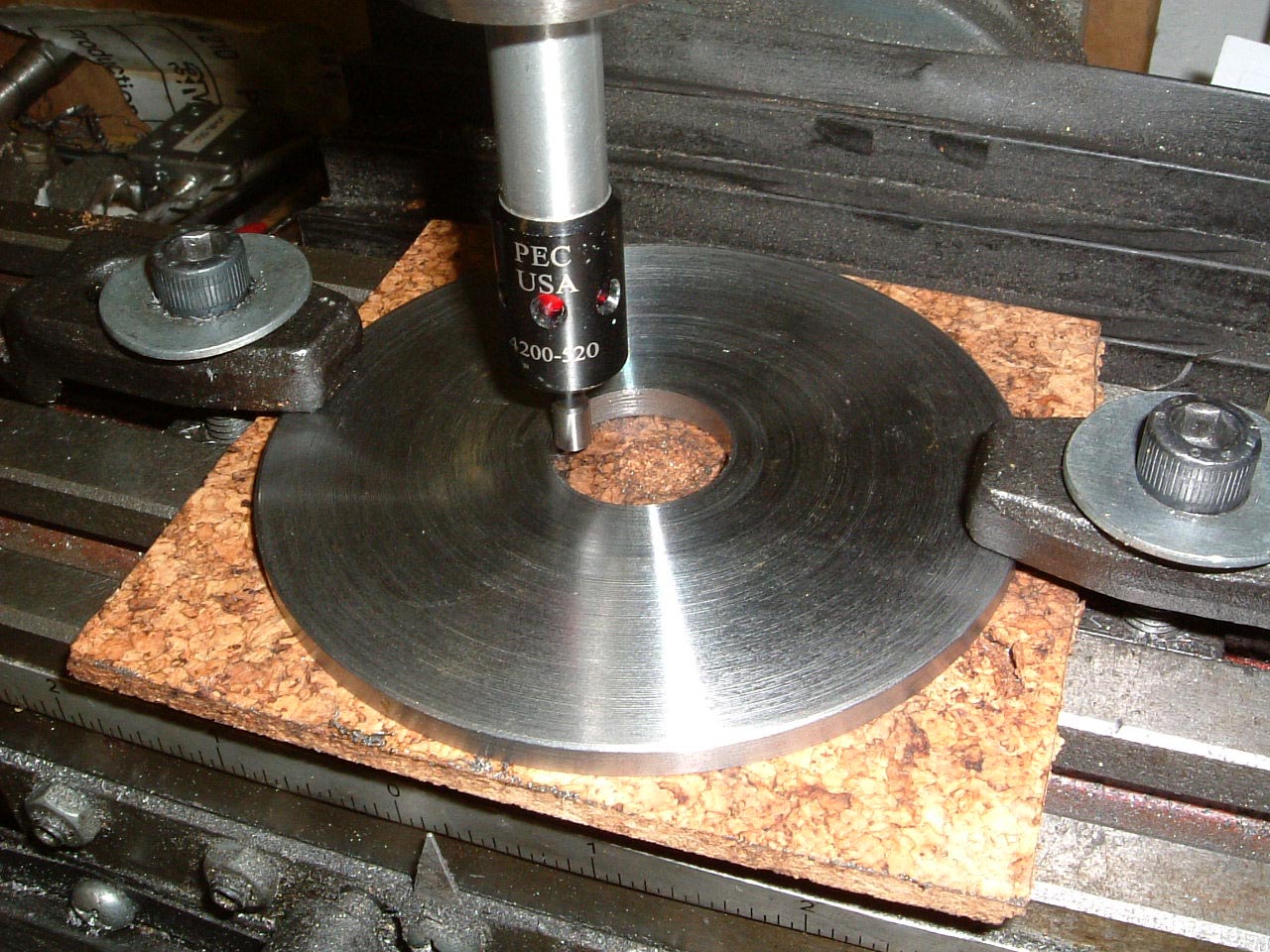
14-May-2005: Some offcuts of cork floor tile are used to hold the plate in, this
allows machining to take place right up to the edge of the plate. |
 |
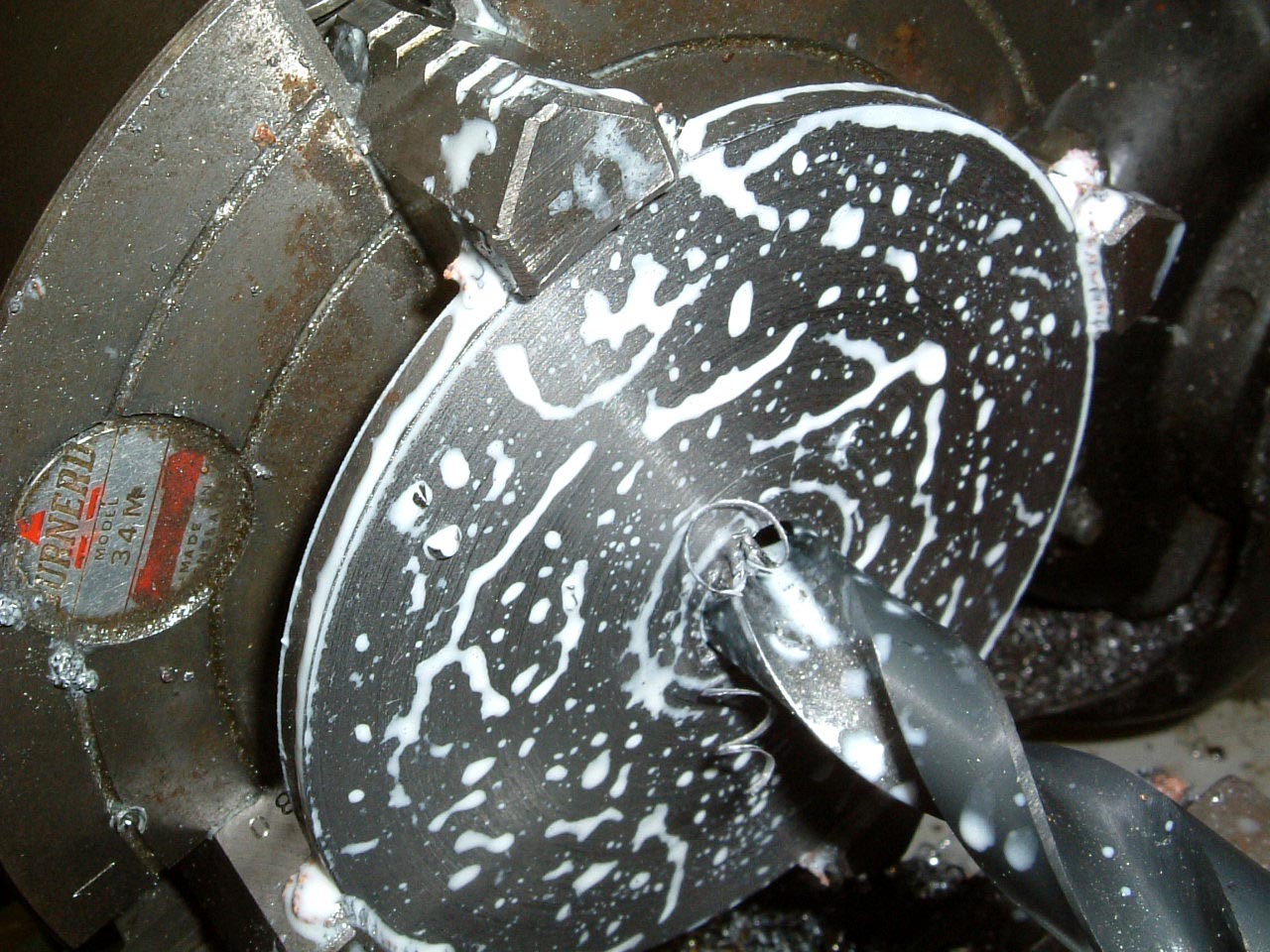
The centre hole is initially drilled, although the final operation is to bore to
size as the hole size must be accurate. A small chamfer is put on one side
of the plate to make it easier to get on the micro worm wheel. |
 |
Using the centre finder to work out the centre of the plate for drilling the mounting holes
- this task needs
to be repeated in the X and Y directions a couple of times as the only references
we have here are curved ones. |
 |
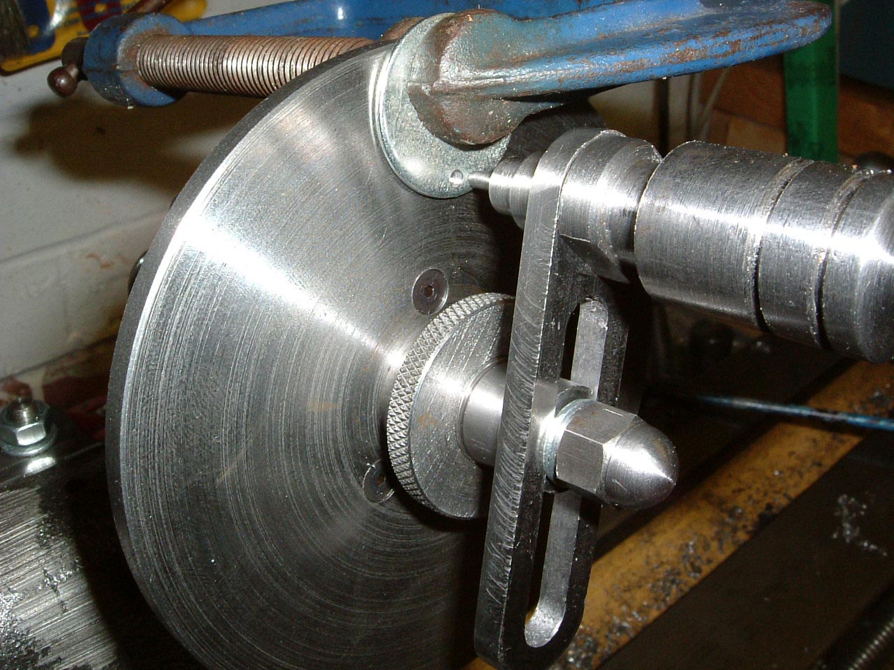
We now have three plates, but none of them have any holes in them. A washer
with a 3/32" hole has been clamped on to make a "1 hole plate". |
 |
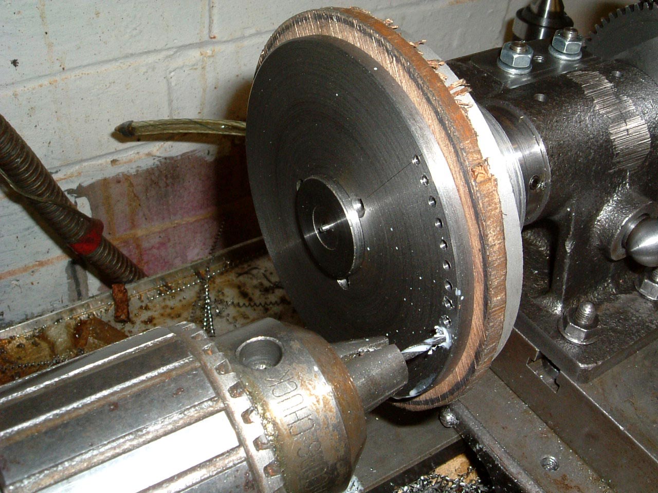
This allows 60 divisions to be made, and hence a ring of 60 holes. Having
60 holes will then allow us to divide into 3600 which is needed to make the 100
graduations on the dial for the micro-adjuster. Incidentally, the plate
being drilled will end up as plate 3, the 60 holes (and micro-adjuster) will
allow plates 1 and 2 to be drilled. |
 |
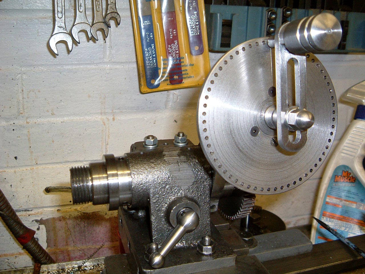
Plate 3 mounted on the VDH to give any division capability when the micro-adjuster
is used, and even without it can divide by 2, 3, 4, 5, 6, 8, 9, 10, 12, 15, 16, 18,
20, 24, 25, 30, 36, 40, 45, 48, 50, 60, 72, 75, 80, 90, 100, 120, 144, 150, 180, 200,
225, 240, 300, 360 and some higher numbers. Maybe I should finished off the sector
arms... |
|