|
|
1: Work head Last updated: 30 Nov 2016 |
|
Looking at the drawings, quite a number of dimensions are omitted, although these are described as non-critical. Even where dimensions have been provided, there are still a few problems... |
|
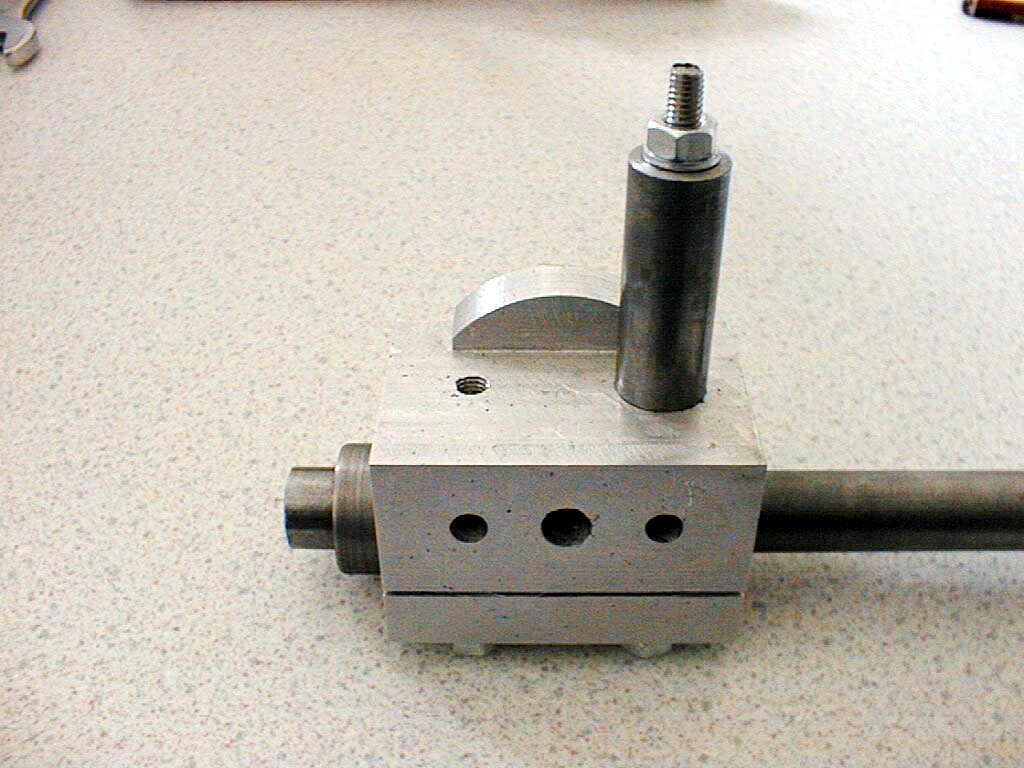 |
10-May-2003: Jacobs used a piece of 2 1/2" round aluminium bar to make his work head, simply by squaring off the round bits and putting all the holes in the right places. My own preference was for a simple rectangular casting machined to size. A stud is shown on the top which will support the column/bracket. Metric fasteners are used, where 1/4" has been called for this has changed to M6, 5/16" has been changed to M8 although the arbor has been left at 5/8" imperial size to fit the change gears! |
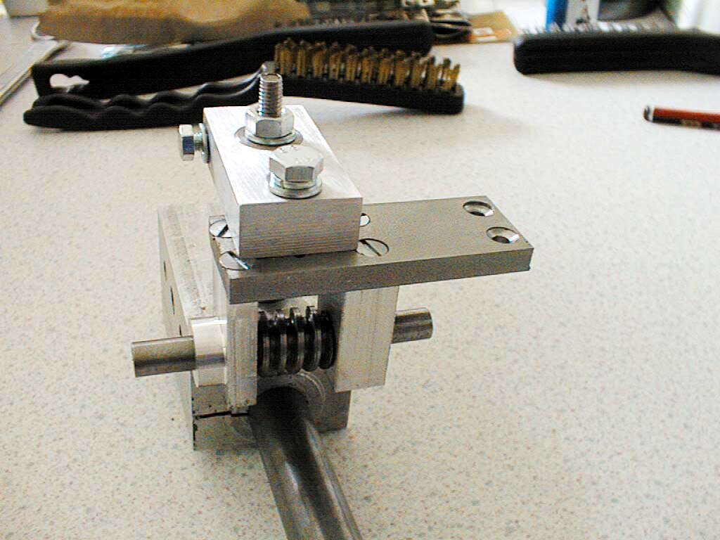 |
The worm carrier bracket has been added complete with left-hand worm cut to mesh with the 20DP change wheel. Again, M4 countersunk screws have been used instead of the BA size originally specified, the top retaining bolt is M6 and the pinch bolt is M5. Not comfortable with this crude mix of metric and imperial, but if it does the job... |
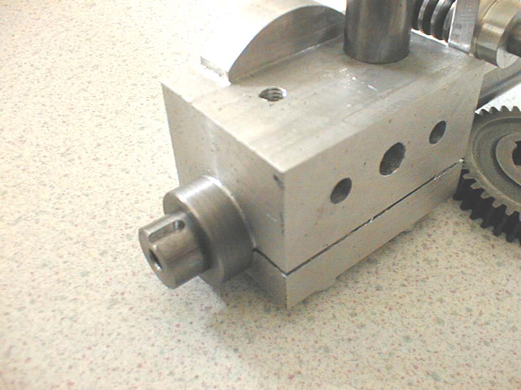 |
The business end of the arbor is 5/8" diameter and a small area has been milled out to allow for a 1/8" wide machine key to hold the blanks in place. The end has been tapped to take an M6 bolt. |
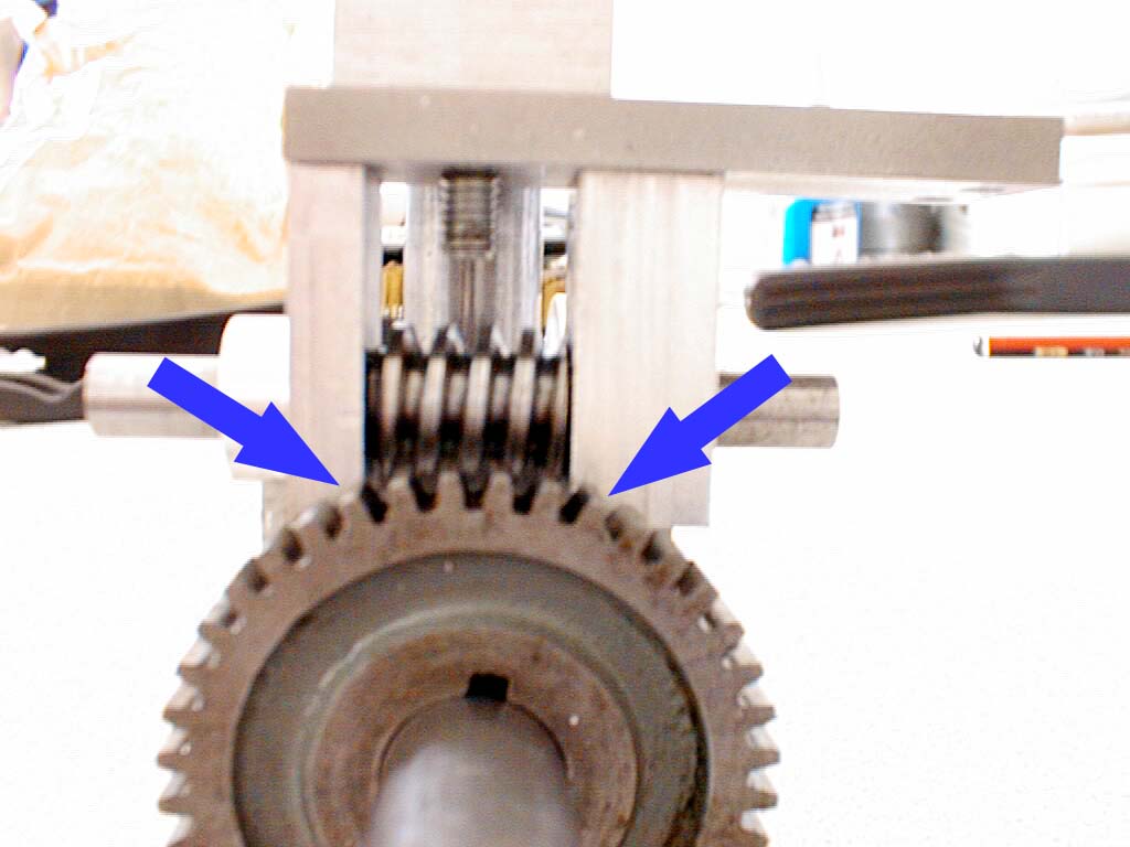 |
Deliberate mistake #1, what's going on here? No way is that gear going to clear the bracket - reference to the original drawings shows that no way it ever would. Having a little think about how to solve this one. |
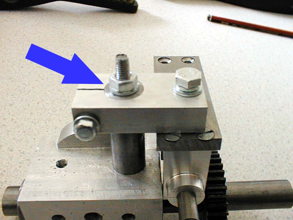 |
Deliberate mistake #2, the 1 1/2" height specified for the column might only raise the bracket enough for a 40 tooth wheel, but it is not going to go high enough to do a 60 tooth in a million years. New stud required, new column required of approximately 2 1/4" height (55-60mm range). |
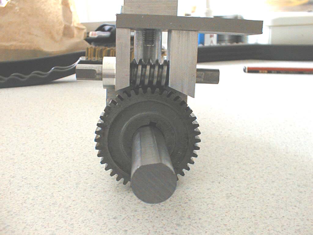 |
Mistake #1 fixed. The problem with clearance on the gear teeth has been solved by putting the holding brackets in the milling machine and removing some material. Note the flat on the shaft, but no means of radially locating the 40 tooth gear. |
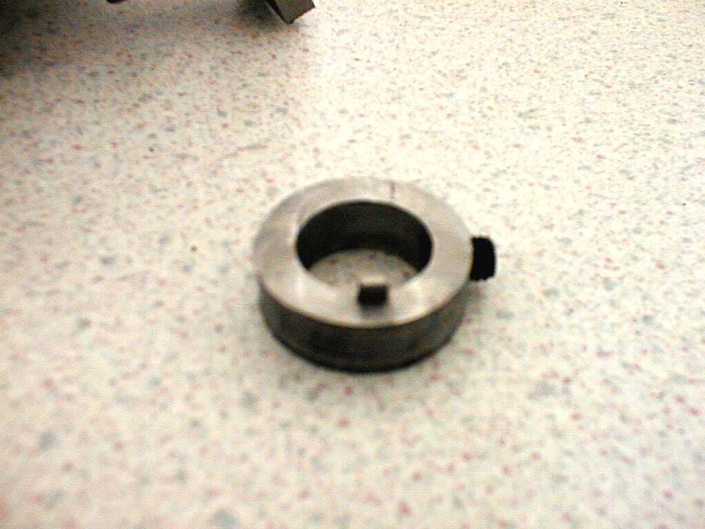 |
After kicking some ideas around, this is what I've come up with for radially locating the change wheels. The collar has been made a little longer than normal, then milled back to leave a 1/8" wide by 1/16" high key which stops the gears from spinning round on the shaft. An M6 grub screw locks the collar solidly onto the flat of the shaft. This arrangement looks fragile, but I will give it a try for now. If they start snapping off, the shafts will get slotted to take 1/8" wide machine keys instead. |
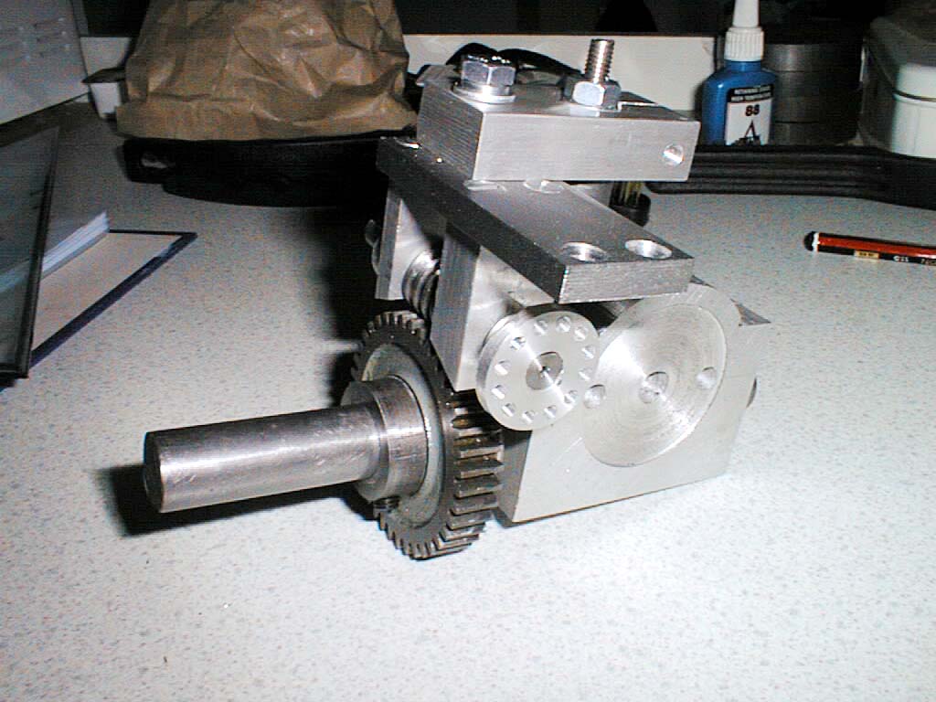 |
There is mention in the original article of a pawl and pawl carrier and a few clues about how it fits together. I've opted for an indexing wheel with 12 holes (interchangeable) through which a pin will fit in the style of a dividing head. This will give 480 divisions with the 40t gear and 720 divisions with the 60t gear. |
Section conclusions There have been a few howlers here, leading me to believe that the original drawings/sketches were never checked out properly. The whole assembly looks fragile although some ideas are springing up for re-design if it doesn't work out to be robust enough when running. That's about all I'm going to do on the work head for now. Next section is the vertical slide... |
|
 The work head holds the gear blank to be cut, this being
mounted on an arbor above which is suspended a bracket and worm gear. The worm gear drives a spur gear on
the arbor, with this spur gear being a normal Myford change wheel typically of 40 or 60
teeth (3/8" thick, 5/8" bore, 20DP).
The work head holds the gear blank to be cut, this being
mounted on an arbor above which is suspended a bracket and worm gear. The worm gear drives a spur gear on
the arbor, with this spur gear being a normal Myford change wheel typically of 40 or 60
teeth (3/8" thick, 5/8" bore, 20DP).
These pages are maintained by Duncan
Munro. All content on this site is Copyright ©2002-2025 Duncan
Amplification.
Warning: These pages consist of images and descriptions of equipment
which can reach high temperatures creating hazardous and potentially dangerous
situations. These pages should not be taken as a step by step guide on how
to construct any items or carry out any particular procedure, nor should any
references to safety contained herein be taken to guarantee safety in all
situations.