|
|
3: Base casting Last updated: 30 Nov 2016 |
|
In the original design, the major part of the base is a length of rolled steel 'U' channel. I'm going for a casting here, but will avoid being ambitious and getting it to retain coolant etc. This part of the hobber has taken a long time (around 6 months) because of other commitments and a workshop refit. Ironically, things have come full circle and replacing the Jacobs structural steel solution with a casting was abandoned due to the amount of extra time it would have taken up. |
|
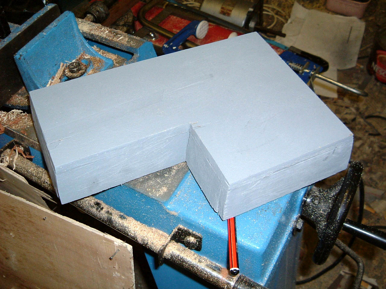 |
17-Jun-2003: This is the start of the pattern made out of 3/8" plywood sheet. The sides are splayed out to give plenty of draft, and a quick coat of primer/filler has been applied to show up the really bad bits. |
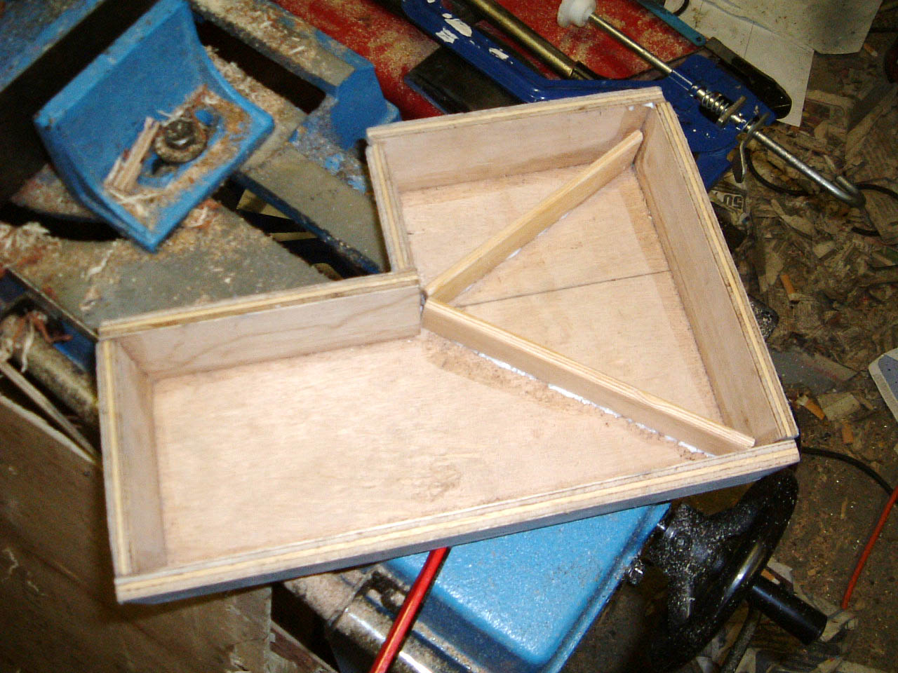 |
The aluminium base will be around twice the thickness of the steel original, but some bracing is going in to provide extra rigidity. Another two or three braces should complete the picture. |
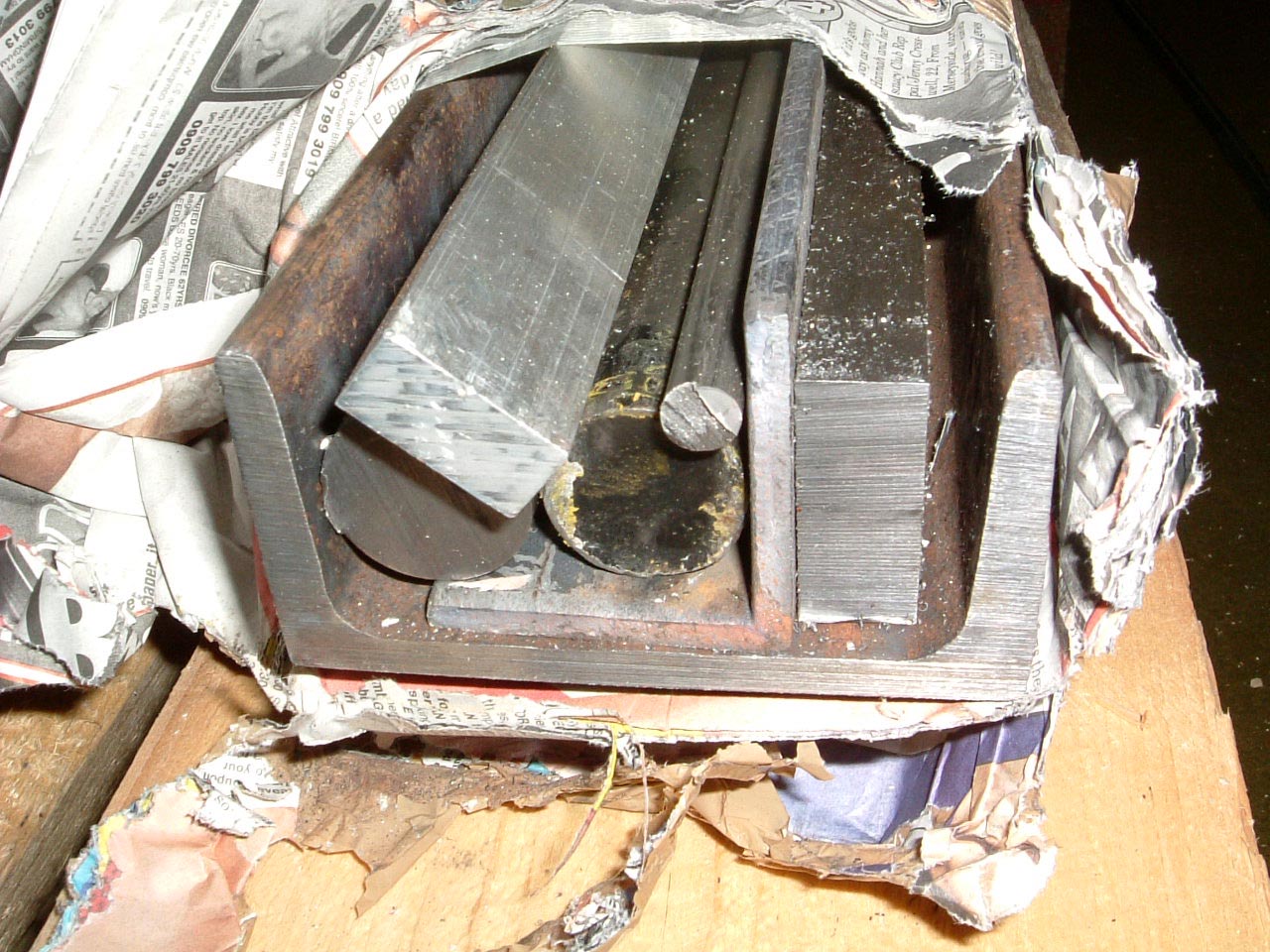 |
21-Aug-2003: After a couple of months of doing nothing due to lack of time I've given in and taken the easy route. Arrived on the doorstep this morning, a 20kg package of bits and pieces from those nice people at Model and College Metals - in there is some 4"x2" channel in the Jacobs style which is going to get things going a lot quicker than the cast ali base. Stay tuned... |
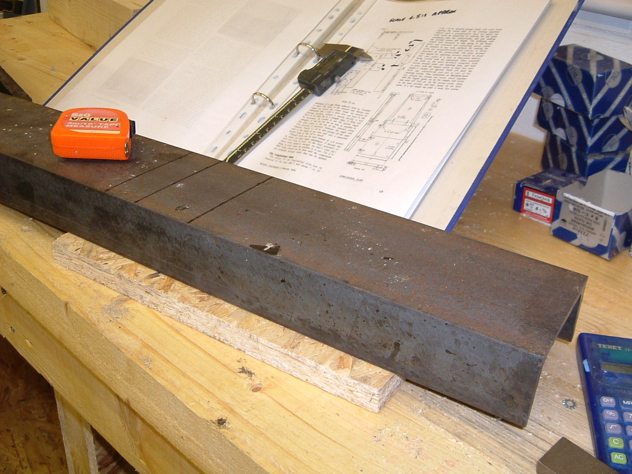 |
07-Dec-2003: Another 4 or 5 months with nothing much happening, it's time to do some more work on the little gear hobber. Jacobs write up says the base is quite trivial and does not give much detail. Even basic dimensions would be quite handy. The article in ME looks to be a scale of 4.5:1 (or thereabouts) so that makes the base 9.75" long. |
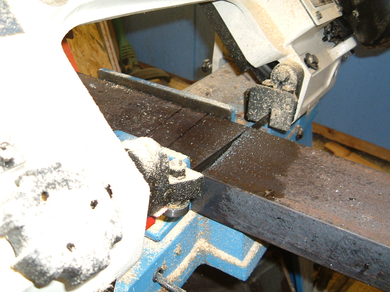 |
The 4"x2" channel goes into the bandsaw which makes for an easy job of things. Marked off are some of the extension pieces that will support the cutting head in alternative positions. |
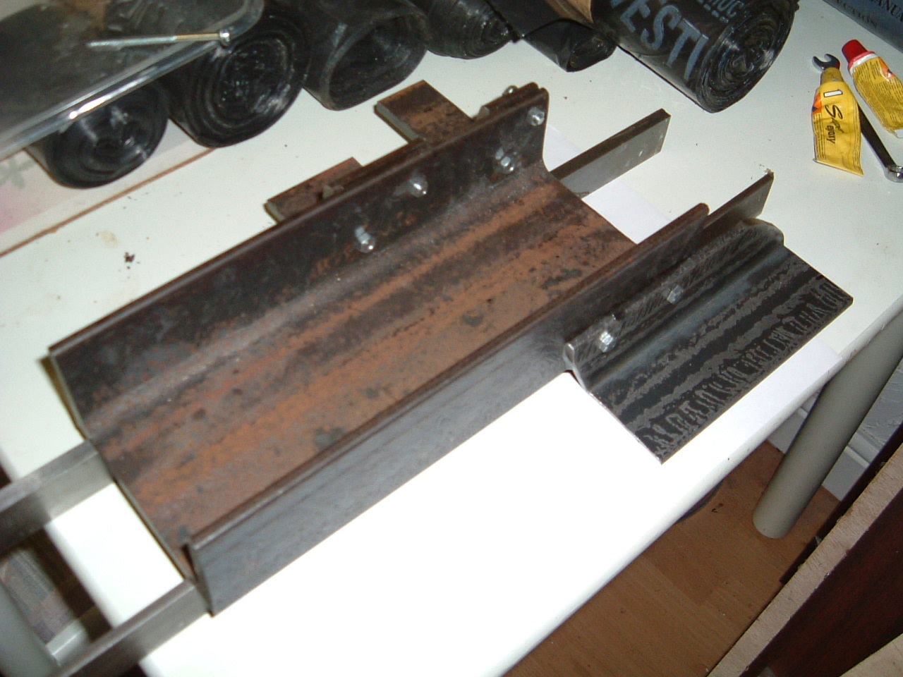 |
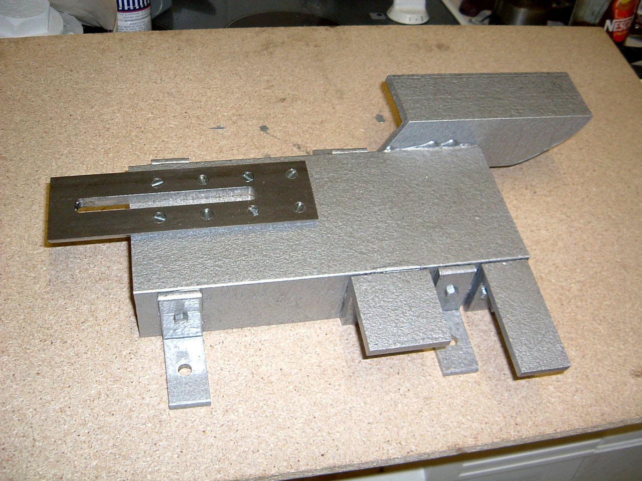
All the parts of the base are held together with M5 bolts and epoxy resin. The whole assembly is shown upside down on a pair of 1" high parallels to get the position correct for the change wheel bracket. Next part will be the dovetail for the longitudinal slide. |
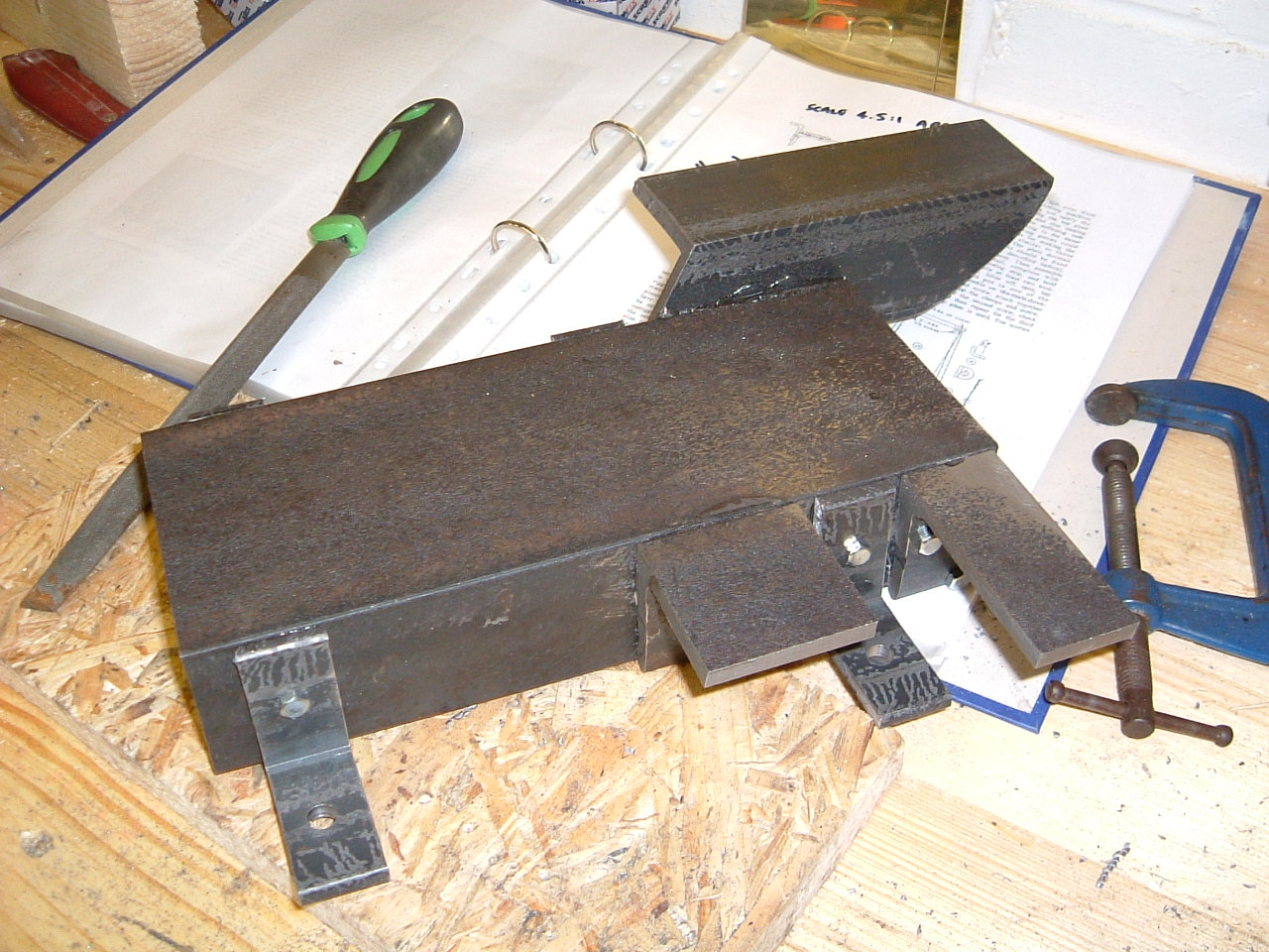 |
09-Dec-2003: I'm not sure how Mr. Jacobs tied the gear hobbing machine to the board it lived on, although one of the ME pictures suggests one or more bolts through the top. Four feet have been cut from 2" angle and attached to the channel with M5 bolts and epoxy. |
 |
13-Dec-2003: Now completed and finished with some hammerite paint. The dovetail was made in exactly the same way as the vertical slide and also features a M6x1 thread. Holes for mounting the cutter and gear plate have not been drilled yet, need to complete these items first. |
These pages are maintained by Duncan
Munro. All content on this site is Copyright ©2002-2025 Duncan
Amplification.
Warning: These pages consist of images and descriptions of equipment
which can reach high temperatures creating hazardous and potentially dangerous
situations. These pages should not be taken as a step by step guide on how
to construct any items or carry out any particular procedure, nor should any
references to safety contained herein be taken to guarantee safety in all
situations.