|
Home
Up
|
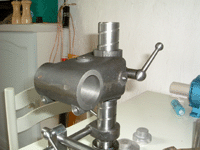
The Wheel Head
The wheel head couples the spindle and the motor together and allows for
height adjustment. It can also be swung radially to present the wheel at
different angles to that normally used.
200: Collar
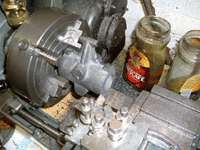 |
22-Apr-06: The collar is being faced so it has a flat end to stand on. |
 |
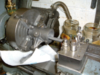
The flat face allows the collar to be set up to have the hole drilled and
reamed for the split collet. With the split collets, the holes for them
are drilled very early on so that the main hole can be bored with the collets
in situ. |
 |
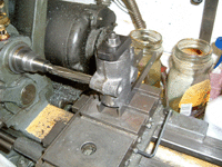
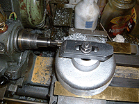
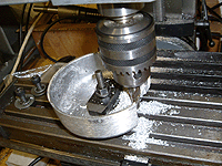
Boring the collar out to 1.250" with the split collet (currently in
one piece) bolted through the casting. |
 |
By bolting the collet in before the main boring operation, it will always
be a good fit. |
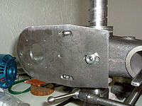
201: Bracket
 |
23-Apr-06: The bracket on the faceplate to get one side faced off -
it only just fits. |
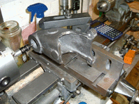 |
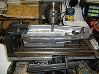
The setup for boring the bracket. Having already drilled the 5/16" BSW holes for the motor
mounting plate, these are being used to secure the bracket to the angle plate. |
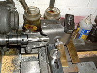 |
Milling some cutouts in the casting. Without these the range of height adjustment is very
limited. |
 |
That's it for now, need some 3/16" steel plate to make the motor mount
from and a larger capacity knurling tool. |
210: Motor mounting plate
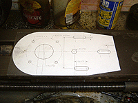 |
17-Aug-06: Marking out is not one of my favourite jobs, so the easy wasy is to print out
what will be on the plate and stick it to the metal. 3M Spray Mount adhesive is used - it's expensive
stuff but does a superb job. |
 |
The plate in position. One bizarre thing is that the holes for the motor mounting don't quite line
up with the pilot holes in the Parvalux SD13 motor. The drawings show a 68mm PCD, the motor measures up around 67.5mm. |
As an update to the motor hole PCD, I had a look at the Parvalux drawings
and they show 67.6mm as the PCD, not the 68mm shown in the drawings and the book.
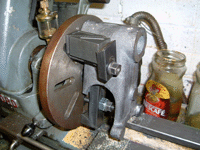
202: Belt cover
 |
09-Sep-06: This is an unwieldy shape to hold the wrong way up, but that's the way it needs to
be to counterbore the securing holes from behind. |
203: Wheel guard
 |
01-Jan-07: The wheelguard is getting the luxury of a split cotter along with all the other assemblies. A 0.5"
hole is being reamed through to hold the cotter blank before boring the 1-3/8" hole in the centre. |
 |
Not quite sure how to tackle the curved cutout, I slot drilled about 7 or 8 holes to get the rough shape and used a boring head
to clean up. |
|


