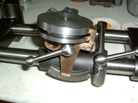
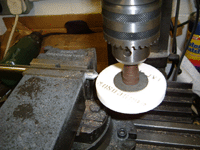
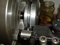
The work head is the movable device which holds the toolbit to or tool to
be ground.
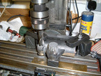 |
29-Apr-06: First task is to make the 9/16" hole for the split cotter.
This must be done first as the cotter will be bored in situ. |
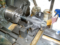 |
Drilling out the hole to 15/16". Note that the cotter is bolted
in place so it will also be drilled/bored. |
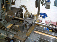 |
Taking out to final size with a between-centres boring bar. The lathe
is too old and worn to risk putting the workhead base in the chuck and boring
it that way. |
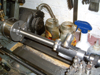 |
The workhead base has been clamped to the front bar so that the spigot can
be machined. Enough grip is provided by the split cotter to prevent
slippage. |
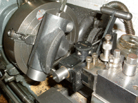 |
Graduating the scale in degrees. This job is so much easier when you
have the right tool. |
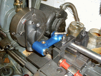 |
And stamping the numbers on. The strange arrangement here is the Universal
Pillar Tool, or part of it, mounted in a V block. |
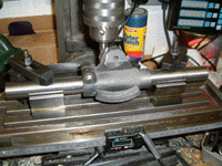 |
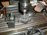
Here the workhead base is being milled to take the pivot bolt which attaches
the tilting bracket. This is very different to the mounting shown in the
book and is a result of recent changes to the drawings. |
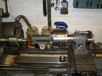 |
The final task is to drill and tap the holes for the dust cover. |
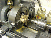 |
01-May-06: Lining everything up to drill the first hole and bore it true.
Everything else is going to be measured from the centre of the mounting hole and the front
face. |
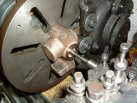 |
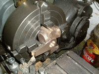
After drilling and facing the front, the boss at the rear is being faced and
the 20 degree taper machined. Both the front and back tapers, and the matching
tapers on the shaft and split washer were done at the same time so at least they will
match. |
 |
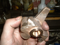
Back to the front and the final sizing up of both the thickness and the
tapered part of the end of the finger. |
 |
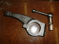
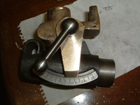
A small amount of material had to be ground out of the back of the casting
to get a reasonable amount of swing. |
 |
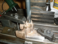
It looks OK and seems to fit together without any binding or gaps.
The redesign of the mounting for the tilting bracket means that the bracket
can be tightened without changing position. |
 |
The next step is to make a 9/16" hole for the cotter - this has to
go in before the 0.500" hole is machined. |
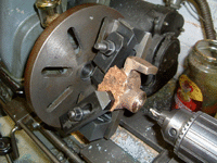 |
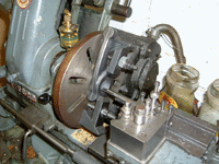
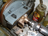
04-May-06: This is the faceplate setup to do the 0.500" hole.
On this setting the outer edge of the tilting bracket (scale marker) can also
be machined. |
 |
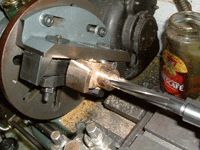
Machining the stop lug - the centre is giving some support
for the interrupted cut. The boss in the centre has already been cleaned up
to a diameter of 1.000". |
 |
The centre has been drilled, bored true and finally reamed to size. |
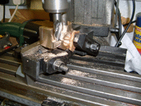 |
All the turning work is done for now - the work has been left on the faceplate as it's easier to
mill the edges square. |
Since the original Chaddock design for the Mk I and Mk II, the rotating base
is no longer made from cast steel. The bulk of the base is a slice of 3-1/8"
mild steel bar supplemented with a square section for the boss and a 1" dia length
of mild steel bar for the spigot.


