|
|
Gear hob Last updated: 05 Dec 2016 |
The mini mill digested
its gearbox recently, so I'm attempting to cut some new gears for it out of
metal. This is a bit of a learning curve for me, so I'm taking my time.
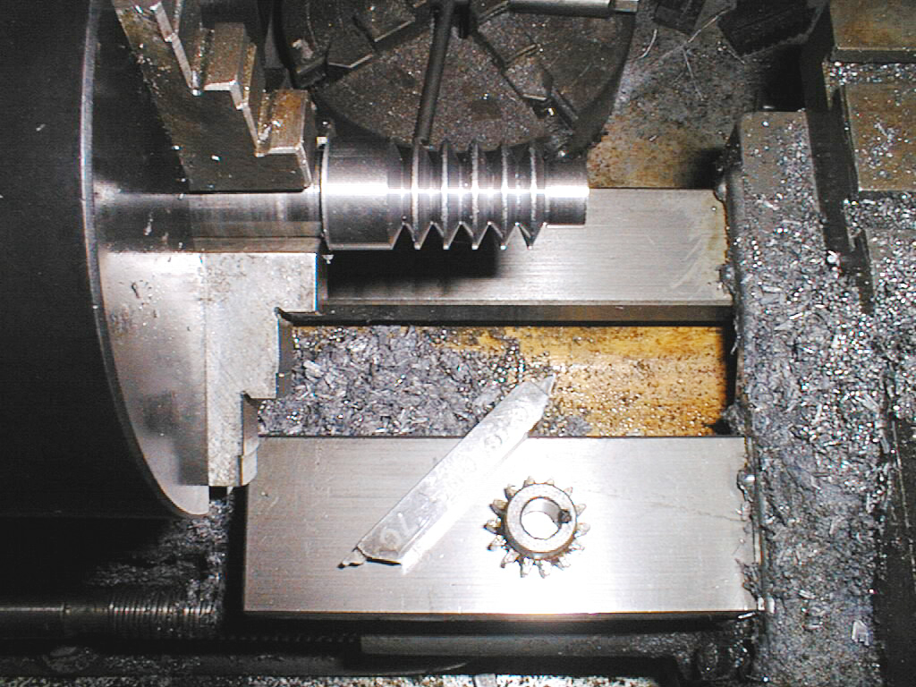
If I make all the replacements Module 1.5 then I only need one hob. Shown below is the Module 1.5 motor pinion from the mini mill for
reference, and the 40 degree cutting tool used to turn the hob. To avoid
chatter, the whole thing was machined at 60 RPM and regularly sprayed with
"suds". It took around 6 hours to turn this little fellow,
and the HSS tool snapped twice. Pictured behind are some mild steel gear blanks. Next step for the hob is heat treatment to harden the silver steel. 28-Mar-2003: Skip the last comment about it all being fine, the hob
is 40 degree pressure angle not 20. Or is it?... Back to the drawing board... Makin' a hob: Attempt #2 The sketch above shows the dimensions as best I can work them out for a metric module
1.5 rack. The rack form will be used to cut the gear.
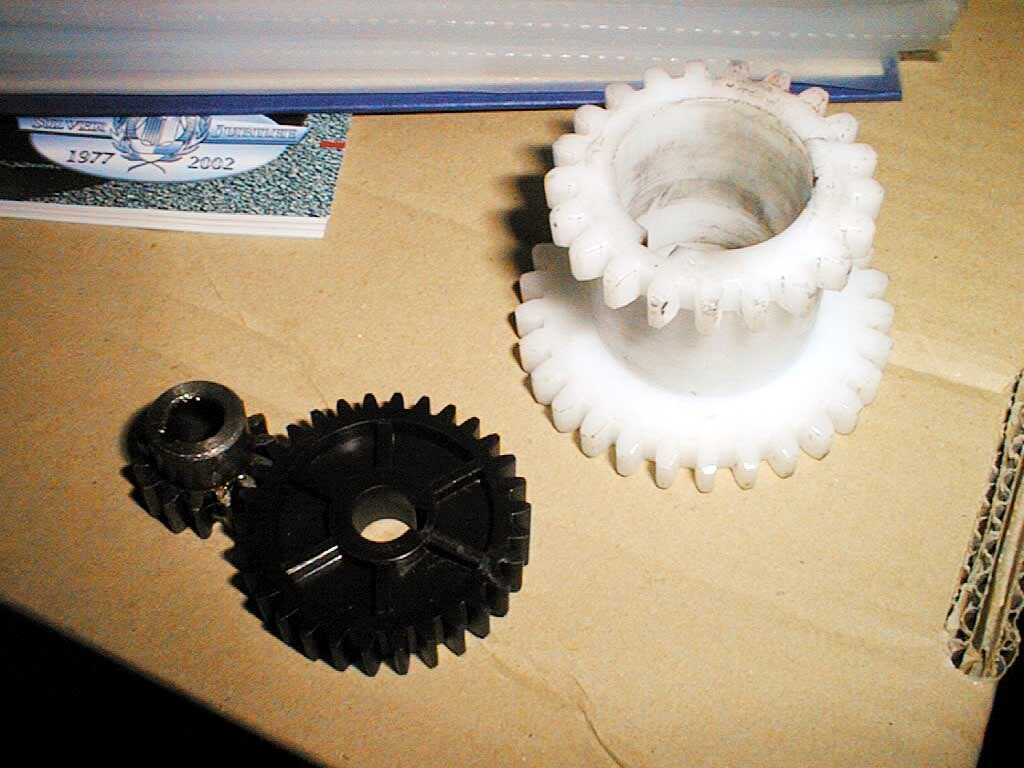
06-Dec-2002: The motor gears are metric module 1.5 as shown of
the far left, the larger gears inside the gearbox don't seem to fit any
known pitch. They are too big for metric module 2.0, and are
slightly bigger than 12 DP.
26-Dec-2002: I've started making a metric module 1.5
hob from some 3/4" Silver Steel (drill rod) which will later be
hardened and tempered.

5-Mar-2003: It's been a while since any developments,
but the hob has now been milled to relieve the teeth using the new rotary table bracket.
There are three rows of teeth, it would probably have been better with 5 or 6.
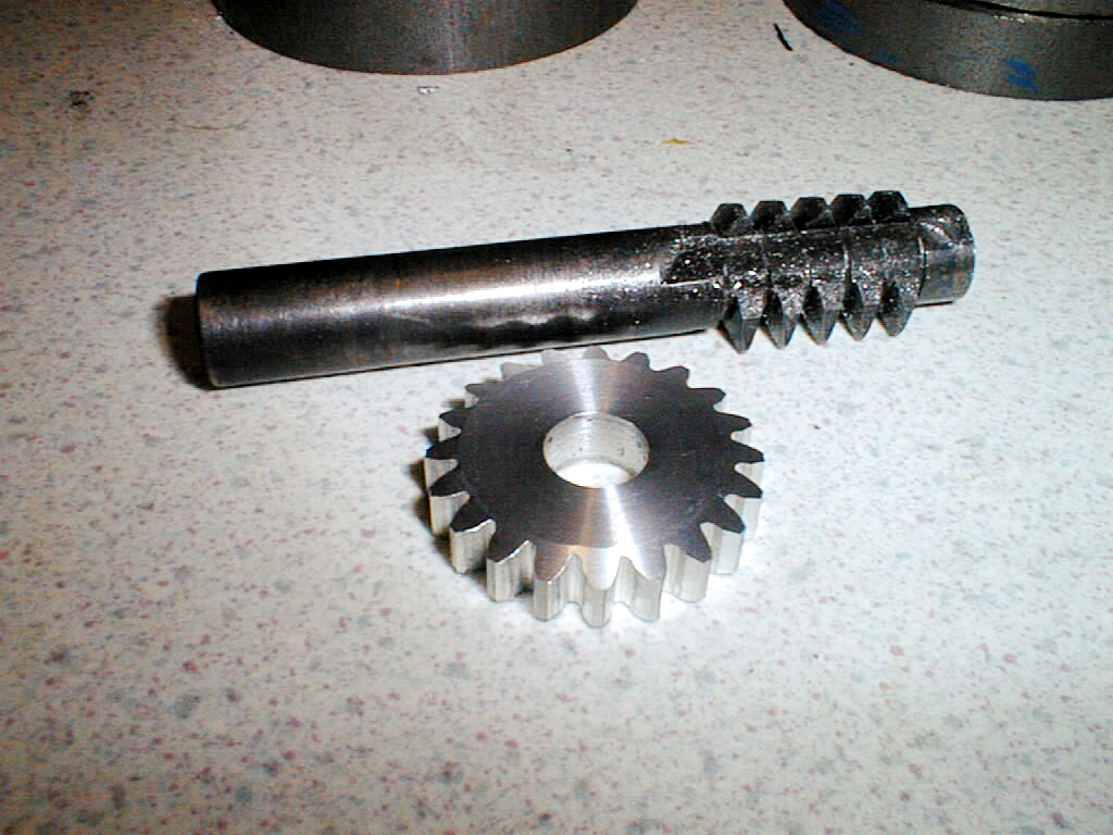
7-Mar-2003: All done, the hob works fine - shown is a 20 tooth metric module 1.5 gear cut with the hob.

4-Apr-2003: Having consulted the useful book on the left and a number of other sources,
the angles on the first hob were almost correct. It's also bent out of shape, so time to make a new one.
If anyone told me it would take a whole four months to get back to square one, I would not have even started this...


Not wishing to spend a couple of evenings turning up another expensive lump of silver steel, the new hob is
going to be made from mild steel and then case hardened - for the amount of use it will get, this will be fine. It will also be removable from the shaft
which in this case is 1/2" diameter. The reason for the imperial size is that any hobs I make up
from now on will fit a Jacobs type gear hobber. A collar with three M5 grub screws, and an M8 nut/washer allow for axial retention although the 1 1/4" hob blank needs to be broached in some way
so that it won't spin round on the shaft.

10-Apr-2003: To get the hob cutting tool correct, a setting gauge is required
which has been marked out to get the correct 20 degree pressure angle (40 degree point). The
material used is 0.7mm steel plate, part of one of those "knock out" panels that cover the drive
bays of new personal computer cases.

The waste has been snipped just short of the scribed lines, and a needle file
used to clean up the remainder. The snipping and subsequent hammer flattening has caused a small
amount of distortion.
These pages are maintained by Duncan
Munro. All content on this site is Copyright ©2002-2026 Duncan
Amplification.
Warning: These pages consist of images and descriptions of equipment
which can reach high temperatures creating hazardous and potentially dangerous
situations. These pages should not be taken as a step by step guide on how
to construct any items or carry out any particular procedure, nor should any
references to safety contained herein be taken to guarantee safety in all
situations.